Similar Posts
A nifty little Matlab code to show why we need to wet the backsides of the membranes
I couldn’t really make sense of what was happening in this post, and in particular this figure threw me for a loop: So to help myself understand the relationship I whipped up a little matlab app to show the relationship a little clearer: Moving the sliding bar on the bottom changes the y-position…
Multi channel, dual chip dialysis device
A two multi-channel chip device was fabricated with gaskets and PDMS caps. The Upper fluidic
AJA film characterization
I used the spectroscopic ellipsometer to measure several wafers deposited using the AJA system. I verified film uniformity as well as film quality using index of refraction as the metric. The term “w/ Bias” refers to an applied RF power over the substrate. The bias adds energy to the surface as adatoms re-arrange during deposition…
HUVEC alignment on SiN membrane under flow
ByHenryHi all, A while back I have posted about my attempt to culture bEnd3 (mouse brain endothelial cell) underflow, which failed to maintain bEnd3 proliferation and did not promote alignment under flow. As an alternative/control, I switch the cell types to HUVEC (human umbilical cord endothelial cells), which is known to do well under flow….
Long Term Urea Clearance in 100% Serum
I ran a 30 hour urea clearance with 100% serum through the single slot dialysis device. The now standard protocol was run. The single slot chip was annealed in the RTP for robustness then clamped into the acrylic/PDMS flow fixture. Ethanol was pumped through the chip for 1 hour, then degassed PBS was pumped for…
Pnc-Si cross section by FIB and cleaving
1) FIB. I tried to get a cross section of the pnc-Si with FIB with Brian’s help. The results are negative. It looks like the ion beam almost “melts” the membrane and destroys the pores instead of cutting. The tool also has in-built Pt deposition capability (from organo-Pt compound). So we tried to make the…
2 Comments
Comments are closed.

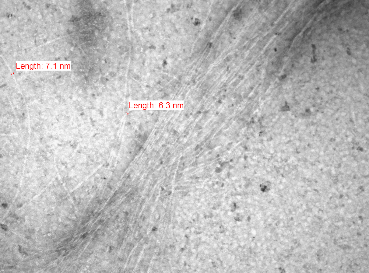
There appears to be molecular structure in these images! In my experience people need to label with larger actin binding proteins to see this type of structure. I know Karen is doing some comparisons on carbon grids.
Could be good.
Here is a useful web page on electron microscopy that uses actin filaments as a reference molecule. The good news is that I think our images show hints of the ‘rope-like’ actin structure you can see in Figure 1.8.
http://www.mih.unibas.ch/Booklet/Lecture/Chapter1/Chapter1.html