Fluorescein transport through transwells in 24-well plate
This post is a continuation of the experiments posted a couple of days ago. In that post, I concluded that absorbance measurements of molecules transported through transwells were not possible if the transwell insert was kept in the 24-well during measurement. This was due to absorbance by the outer walls of the 24-well plate and the insert itself, thus ‘contaminating’ the hypothesized annulus between the outer wall and the insert.
Here, I measured transport in fluorescence mode with careful controls. Specifically, I took an initial measurement (time = -1 minute) of all samples with buffer (HBSS w/10mM HEPES) to get the autofluorescence of buffer, 24-well plate plastic and transwell/Sepcon plastic. I then added 0.02% sodium fluorescein to the “donor wells” of transwells and immediately started a 1.5 hour kinetic fluorescence scan (10 minute intervals). Receiver volume was 1.5 mL. Fluorescence scans were 10×10 open circles with a 1000um border. The gain was calculated from a well with 0.02% sodium fluorescein alone.
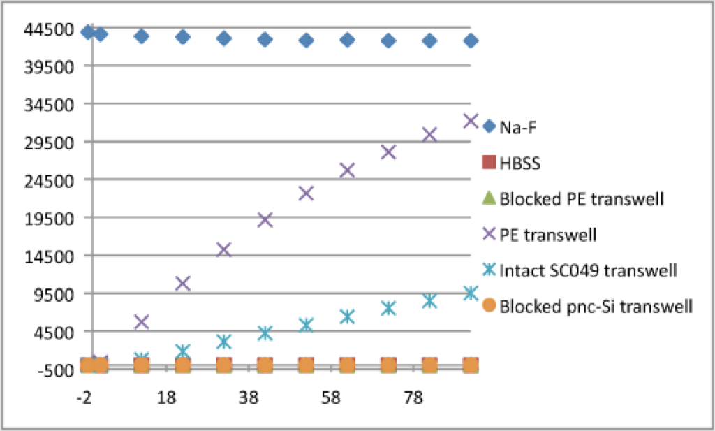
The raw data (no blank reduction) shows that 0.02% sodium fluorescein (Na-F) remains ~ constant (which is critical because the gain is set off this well). Also, Na-F transport through the commercial and pnc-Si transwell is apparent. In fact, this transport profile roughly matches that of rhodamine through commercial and pnc-Si transwells here.
I was also interested in the transport behavior at short times (I removed the Na-F data since it is ~ 400x more fluorescent than these samples):
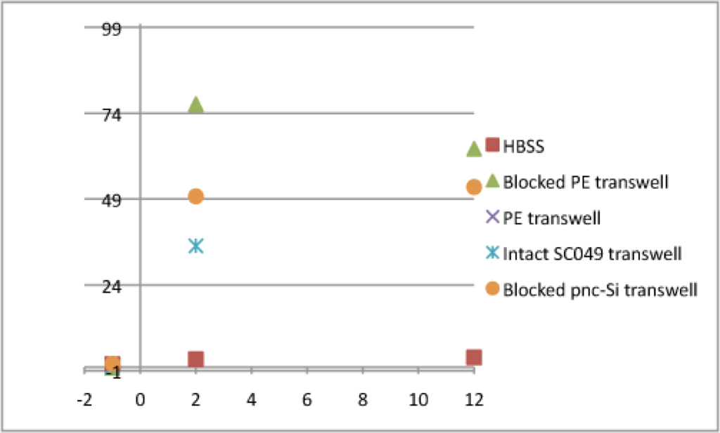
This graph illustrates the autofluorescence of inserts and very short time transport. It also underscores the importance of clever controls in these experiments. Three main points: 1. Immediately after adding Na-F to the “upper wells” of pnc-Si Sepcon transwells (orange cicles, blue X’s), the fluorescence jumped up to ~40-50 RFU. The blocked pnc-Si transwell (orange circles) is a pnc-Si chip with membrane slits that I had painted with clear nail polish. The nail polish prevents Na-F transport but allows fluorescence to leak from the upper well, through the membrane slits and into the lower well. Therefore, a blocked pnc-Si transwell is the appropriate negative control for pnc-Si transport studies in this system. 2. The blocked PE transwell (green triangle) is a commercial transwell that I painted with nailpolish, thus allowing fluorescence cross-talk but no transport. Immediately after adding Na-F the fluorescence increased even more than pnc-Si to ~ 75. This is because commercial transwells are more transparent than Sepcons. 3. Notice that the first data point for PE transwells is off scale. This shows that a good amount of Na-F has transported across the PE membrane from the time it took me to pipette it into the upper well to the time the Tecan measured that well. It takes ~ 15-20 seconds to do a 10×10 open circle scan of each well in a 24-well plate, so there is a lag in this setup right now. I’m not sure how important this is since we’ll likely be calculating permeability coefficients from ~ 1 hour of data.
I then plotted the fluorescence of these controls over the entire experiment:
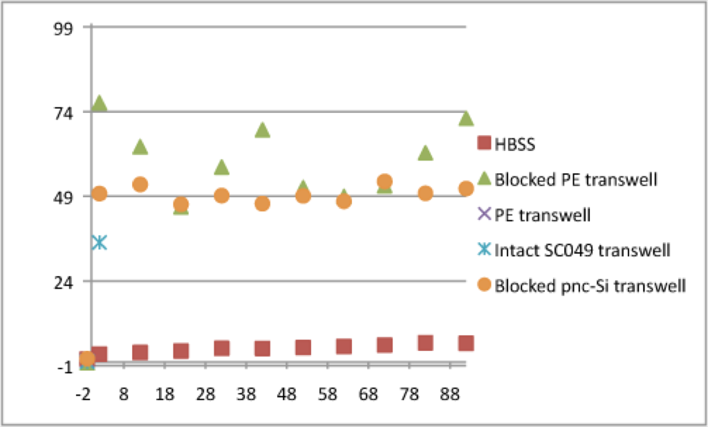
Score! The blocked pnc-Si transwell and the blocked PE transwell fluorescence was steady after the initial jump seen in the previous graph. (I’m not sure why the PE transwell is noisier. But keep in mind that the upper limit of the RFU scale in this experiment is ~ 41000 so oscillations of ~ 10 aren’t too bad). Furthermore, these RFU values are significantly lower than the actual fluorescence that had traversed both PE and pnc-Si membranes (see 1st graph). Therefore, by including blocked transwell and pnc-Si inserts in these experiments as controls (and then subtracting these as blanks), the transport of fluorescent molecules through transwell membranes can be measured “in situ”.
Great!
I think we need to see the effects of turning on the orbital in a dedicated experiment and then we are ready to make some permeability measurements with this tool.
To realize the benefits of pnc-Si we will soon need membranes with higher active area.