Microfluidics in Hemodialysis Project
The purpose of the fluidics in our hemodialysis system is to move the sample to and the retentate away from the membranes. The dialysate (permeate, filtrate) will be handled passively in the initial designs and therefore do not require fluidic manipulation. The parameters influencing the movement of the sample past the membranes include channel geometry (volume and height), flow rate, fluid characteristics, flow uniformity in the channels. Flow uniformity in identical channels is affected directly by the channel architecture and fluidic delivery.
The selected architecture for our system is for parallel channels connected to one inlet and one outlet. It is imperative that the flow in all the channels be uniform. Flowing the majority of the sample through a small subset of channels reduces the overall effectiveness of the dialyser.
An initial mold (see Figure 1) was created to flow the sample past the membranes in a straight forward manner. A COMSOL model was created to visualize the flow velocity of the fluid through the channels as seen in Figure 2. It is possible that very little fluid will flow in the outboard channels.

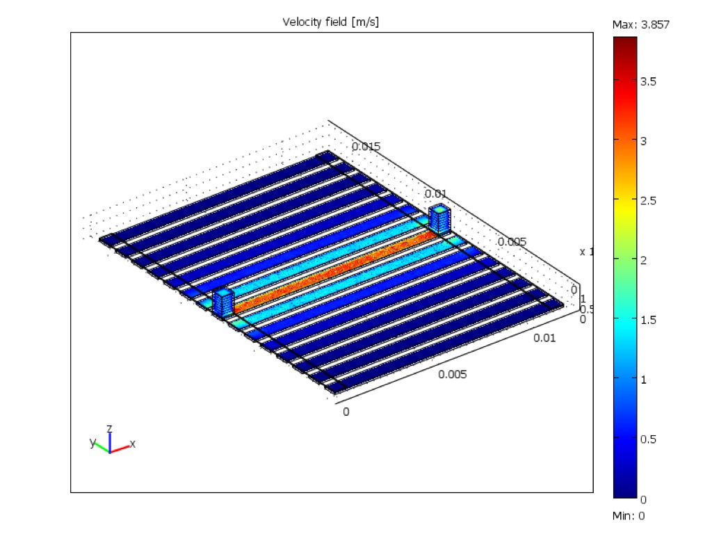
A flow test device was created, using a chip with damaged membranes, to test this model. The damaged membranes were sealed by bonding a blank of PDMS to the membrane side of the chip with a fluidic PDMS layer bonded to the channel side.DI water was pumped through this device. Figure 3 shows the fluid from which results from the “Bus bar” approach. The outboard channels have a longer path and therefore will experience slower flow rates since the fluid velocity is proportional to the pressure drop and inversely proportional to the channel length.

A second COMSOL model was quickly created to test the hypothesis that a fan-out shaped inlet/distribution channel would equalize the flow through all of the channels (see Figure 4). The model illustrates that the low velocity is equalized. Strictly speaking, the fan-in design of the outlet channel may not be necessary for equalized velocity flow, this has not been tested and it can’t hurt. In this design the fan-out channel is 50 microns deep. A model with 500 micron deep fans was created and showed equal flow through all channels (see Figure 5). Clearly there are trade offs with flow equality and fluid volume etc. and these will need to be addressed in the next design revision.
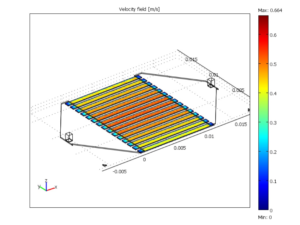
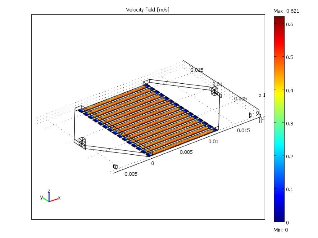

Figure 6 is an image of a fluid front over a honeycombed nitride reinforced membrane. Soon we will be imaging flow through these membranes.
Next Steps:
Analyzing the design tradeoffs for equalizing flow rates through parallel channels.
Image fluid flow though pnc-Si membrane channel.
Linking fluid flow analysis with diffusion through nano-porous membrane into static fluid chamber (see Figure 7).

Dialysate composition book chapter:
http://www.kidneyatlas.org/book5/adk5-02.ccc.QXD.pdf