shear stress reduction via pnc-Si: analytical solution
Hello everyone, presented here is a theoretical perspective on the shear stress reduction enabled by our shear-free microfluidic system.
Briefly speaking, the shear-free microfluidic system consists of three main components: a flow compartment, the pnc-Si membrane, and a shear-free compartment. The membrane attenuates the fluid flow from the flow compartment to the shear-free compartment while permits the material transport between the two compartments through diffusion.
To estimate the shear stress reduction achieved with the use of the membrane, we have derived an analytical solution (collaborative effort of Jim, Rick, and Tejas) and performed a COMSOL simulation to predict the magnitude and the distribution of shear stress in the shear-free microfluidic system. In addition to matching the same shear stress distribution produced by the COMSOL simulation, the analytical solution also predicts the same order of magnitude of shear stress. In this post, we will summarize the analytical solution.
Analytical Solution:
First, we will simplify the shear-free microfluidic system to 2D by taking a cross-section along the direction of flow, as shown in Figure 1A below:
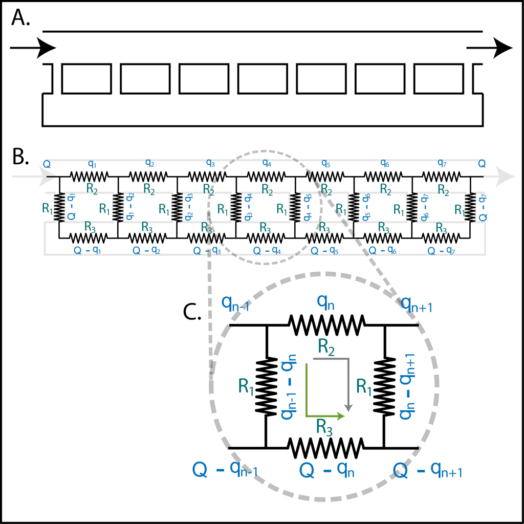
The top and the bottom horizontal channel represents the flow and the shear-free compartment, respectively, and the vertical channels that connect them represent the through pores in the membrane. If we assume the pores to be cylinders of equal diameter and length that space out in equal distance, then the shear-free microfluidic system is analogous to the circuit diagram shown in Figure 1B.
The current flowing through this circuit can be generalized by considering the circuit loop shown in Figure 1C. The voltage drop along the circuit defined by the green arrow is equal to the voltage drop along the circuit defined by the gray arrow. Thus R1(qn-1 – qn) + R3(Q – qn) = R2(qn) + R1(qn – qn+1). Expand and rearrange, we get the following recurrence relation that describes the current flowing across the nth section/repeat of the flow compartment: qn = Rp(qn-1) + Rp(qn+1) + Rs(Q), where Rp = R1/(2R1+R2+R3) and Rs = R3/(2R1+R2+R3). In a sense, Rp represents the ratio of flow reduction contributed by the pore, and Rs represents the ratio of the flow reduction contributed by the shear-free compartment. The flow in the nth section/repeat of the shear-free compartment, as shown in Figure 1C, is just Q – qn.
To describe R1, R2, and R3, we can resort to the Hagen-Poiseuille equation, which stated that the pressure drop along a channel is equal to the product of the input flow rate and the resistance defined by the channel dimension. For cylinderical channel, the resistance is 8uL/r^4, where r is the cylinder radius, L is the channel length, and u is the viscosity of the fluid. For rectangular channel, the resistance is 12uL/(wh^3), where w and h are the channel width and height.
To describe the distance between each pore we will use the pore-diameter and the membrane porosity. If we take a cross-section of the membrane and look from the side, the ratio of the length of pore to the length of “non-pore” can be approximated as the square root of the membrane porosity. The distance of non-pore can then be obtained by ((1-sqrt(porosity))/sqrt(porosity))*pore-diameter.
We implemented the iterations of the recurrence relation to obtain each qn via MATLAB and obtained the following distribution of fluid flow, shown in Figure 2 below (Note that the arrow size also indicates the magnitude of the flow):
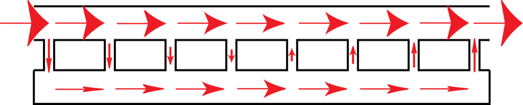
Essentially, as the flow from the flow compartment passes through each pore more and more flow goes into the shear-free compartment. However, due to the conservation of mass, after the midpoint of the system the flow in the shear-free compartment has to gradually go back up to the flow compartment. Thus the maximum flow in the shear-free compartment always occurs at the midpoint of the system. If the system is long enough, eventually the flow at the shear-free compartment will plateau to the maximum value of R2/(R2+R3)*Q, where Q is the input flow rate. How quickly do the shear-free compartment reaches the plateau depends on how resistive the pores are. As long as R1 is sufficiently large the flow in the shear-free compartment will never reaches the plateau, and the shear-free compartment will be relatively “shear-free” for a given compartment length.
NOTE: 1. There most likely is a closed-form solution to the recurrence relation of our analytical solution and we are currently looking into it. Meanwhile, the analytical solution is solved by iterations via MATLAB.