Electrochemical Testing of Ultraporous Membranes as Separators in Mild Aqueous Supercapacitors
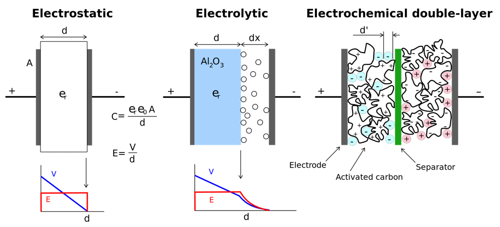
I’ve been thinking a lot about energy storage lately, and I think I’ve found a potential use for pnc-Si in Supercapacitors. What is a supercapacitor? As the name suggests, it’s a double-layer capacitor (EDLC) with very high capacitance values (1-500+ Farads) or a million times more than that of a typical dielectic capacitor. An electrolyte polarizes to account for the charge on each plate of the capacitor, forming an electrical double layer. Activated Carbon and platinum are used to vastly increase the surface area, thereby increasing the capacitance (remember 
J. Electrochem. Soc.-2012-Laforgue-A929-36
“ The basic principles to obtain a competitive EDLC is to collect all the following performances: high ionic electrolyte conductance, high ionic separator conductance, high electronic separator resistance, high electrode electronic conductance, large electrode surface, low separator and electrodes thickness.”
The key feature I’m interested in is the separator layer. It’s purpose is to prevent shorts across the very closely spaced layers. Ideally it should have a very large ionic permeance to allow the electrolyte to diffuse between the capacitor plates, as well as thinness, and hydrophillicity. The separator layer doesn’t contribute to the power storage of the device, but is a source of loss in the system, providing some resistive loss in the capacitor, referred to as equivalent series resistance (ESR). General trends indicate that higher porosity and bigger pore size are correlated to lower ESR, but I think this is confounded with the permeance of the membrane in this paper.
From the paper: 


I think we can conceive of a membrane that has been surface coated with a hydrophyllic agent, that is 500x thinner than the current 25-30 micron separators, with really high permeance (130-900 
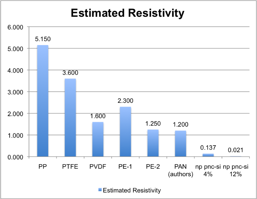
(about 10-100 times less separator resistivity).
I think we could do a rudimentary assessment; we could effectively use my devices with platinum electrodes or activated carbon, by filling the chamber with the specific electrolyte and determine the ESR. Maybe it is worth making an overture to the authors to use the device on their own testing platform?
Caveats: Does the membrane interact with the electrolyte? Will it dissolve over time? Common electrolytes are KOH, Na2SO4, though there are non-aqueous electrolytes too. I assume the silicon itself is a decent electrical insulator, but I’m not sure. The graph itself is just a theoretical estimate; actual values are much less than what the graph would suggest. Ideally, these membranes are flexible (to support winding, increasing the surface area of the capacitor) and a free standing membrane might be more attractive.