Mapping Flow Patterns in the ALD
In this post I’ve detailed my attempts and eventual success (with Josh’s help) to get the ALD to coat TEM grids without blowing the delicate chips around. The actual technique is at the end of the post, beginning with the picture of two valves.
We use the Cambridge Nanotech ALD system for two purposes. First, as a pore size tuner that allows us to adjust the sieving behavior of the membranes, and second, as an insulating layer to keep metal films from leaking voltage into solution in my planned nanofluidic transistor. It’s worth noting as well that 3 nm of alumina can completely negate surface charge as well (paper), so in the future we may coat membranes so that we don’t need to worry about surface charge.
In my previous post on using the ALD for occluding pnc-Si pores, I had a great deal of difficulty making sure that my small chips weren’t blown around the chamber. The ALD is really designed for depositions on entire 4 or 6″ wafers, and we’re pushing the limits of the system when we coat individual 5.4 mm x 5.4 mm Sepcon chips, or worse our 3 mm diameter TEM grids.
I’ve determined that the problem is the initial pumpdown of the system. The actual ALD gas pulsing doesn’t seem to move the chips at all. There are several ways to minimize the harshness of the pumpdown, and to quantify them I’ve used an array of junk TEM grids I had lying around.
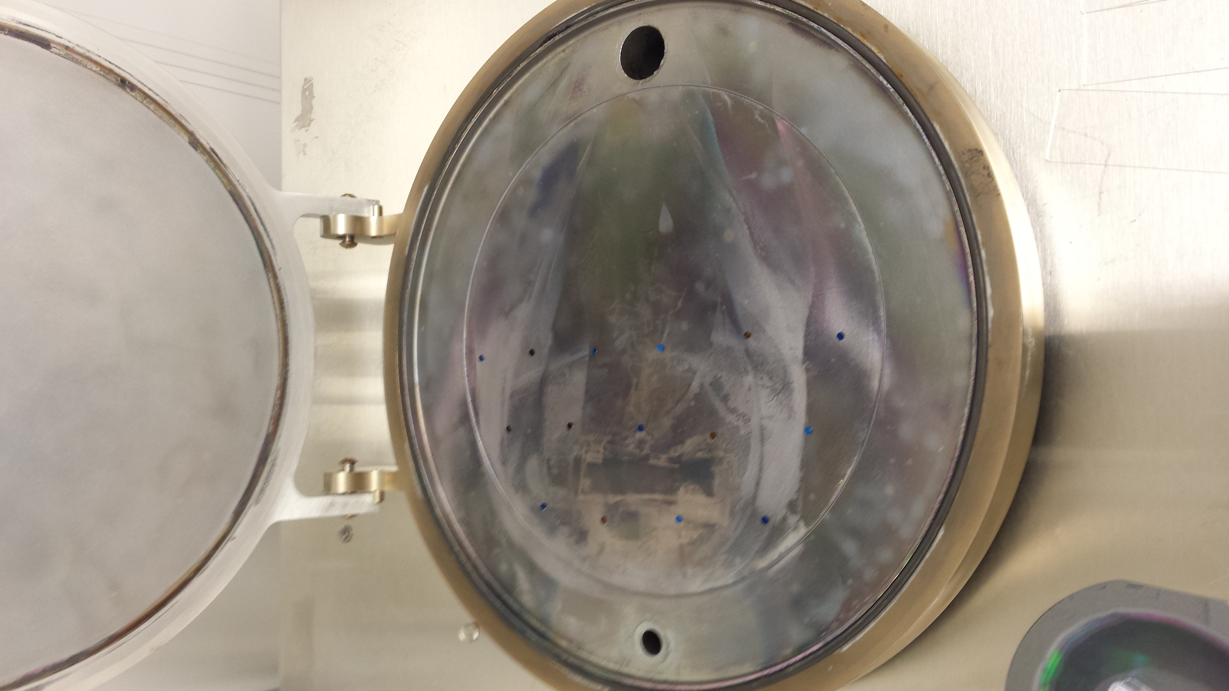
First, a standard pumpdown. All I did was press “pump” on the ALD labview user interface. The chamber gives an audible “whump” and the lid noticeably compresses. Below are before and after pictures of this standard pumpdown (before/after):
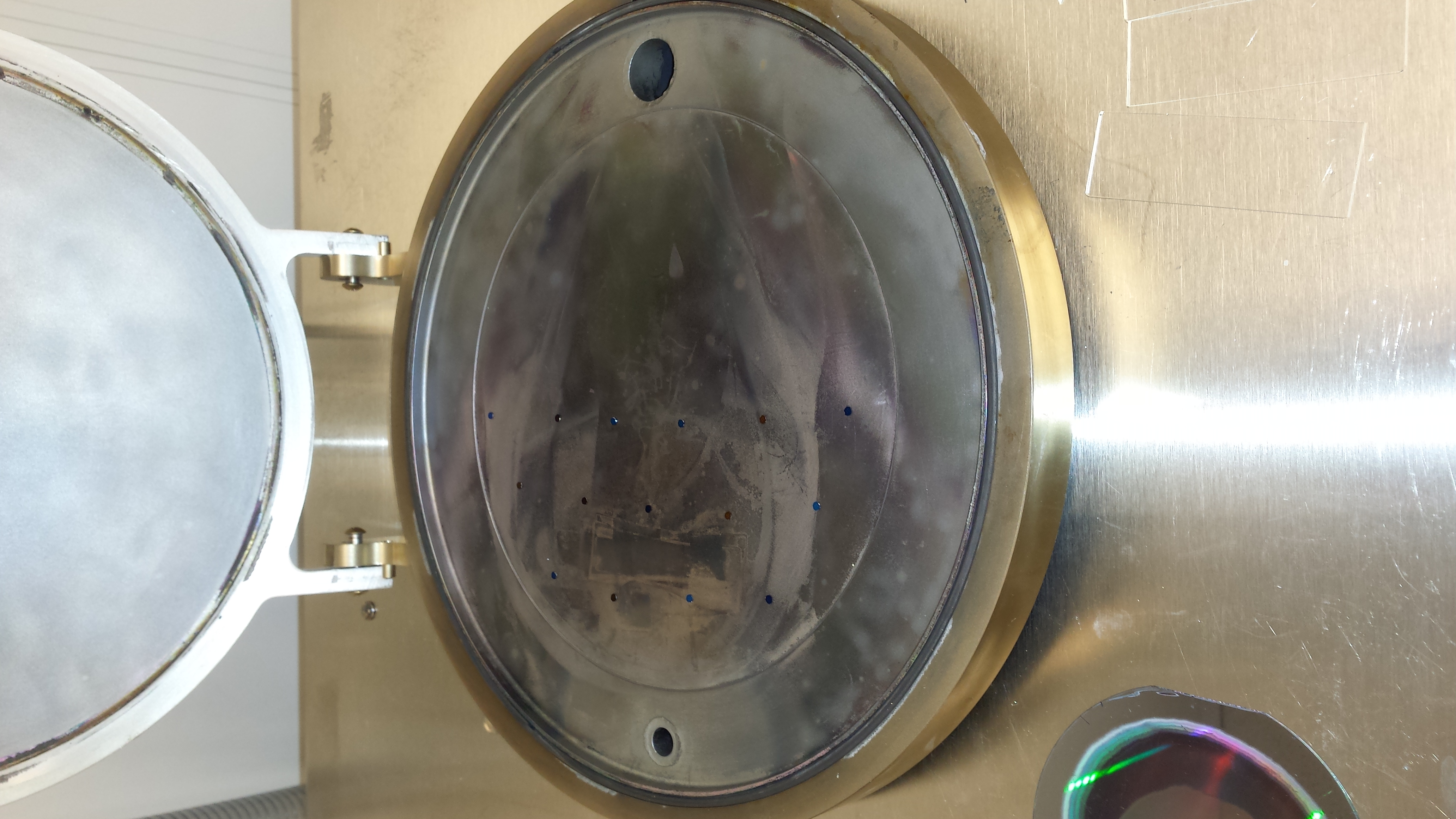

As you can see, several of the TEM grids flipped over, and nearly all of them moved (although the ones in the back, near the hinge, seemed relatively stable).
Next, I tried pressing down firmly on the lid of the ALD while clicking pump, like so:

This worked better (two sets of images)
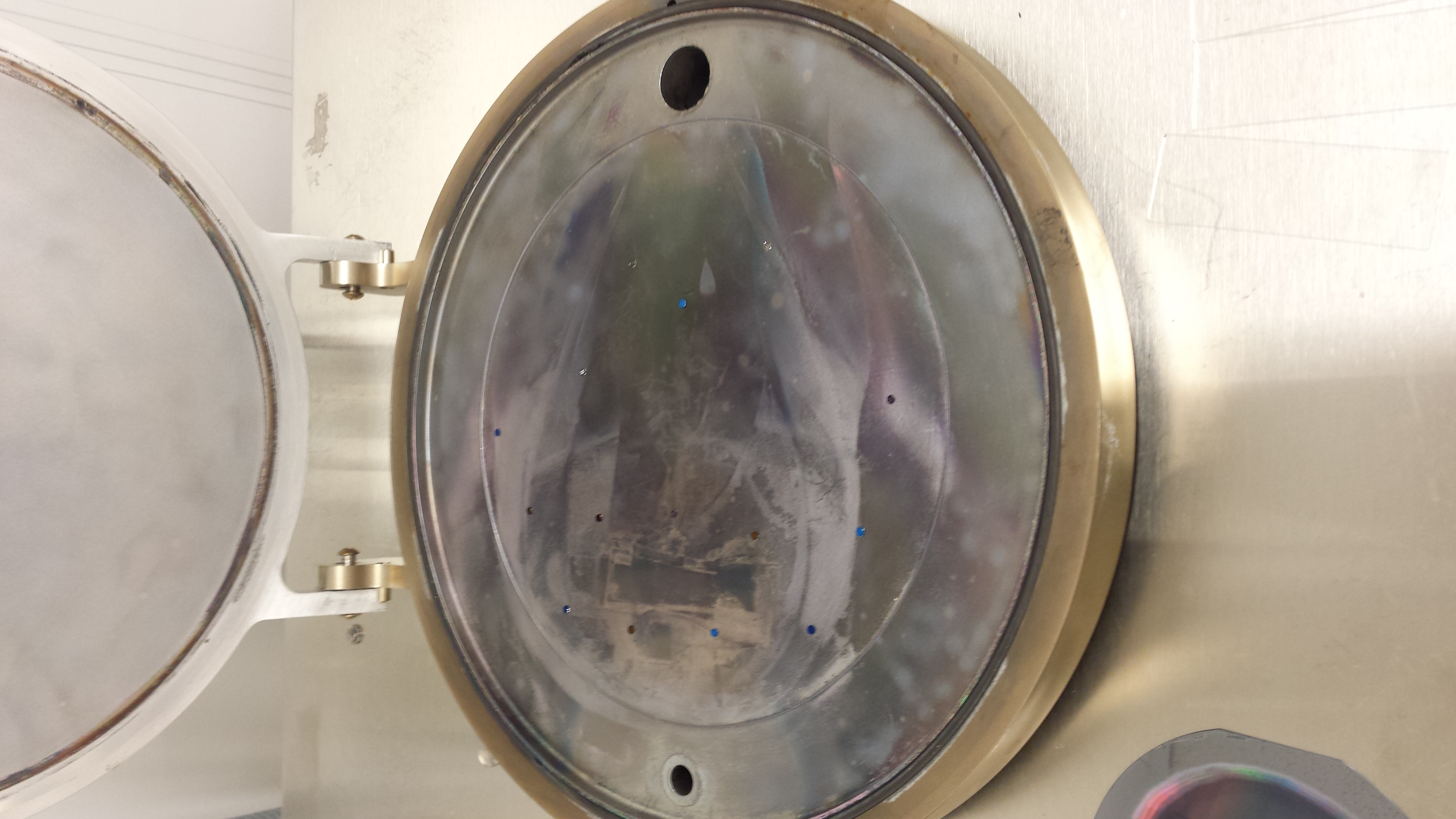

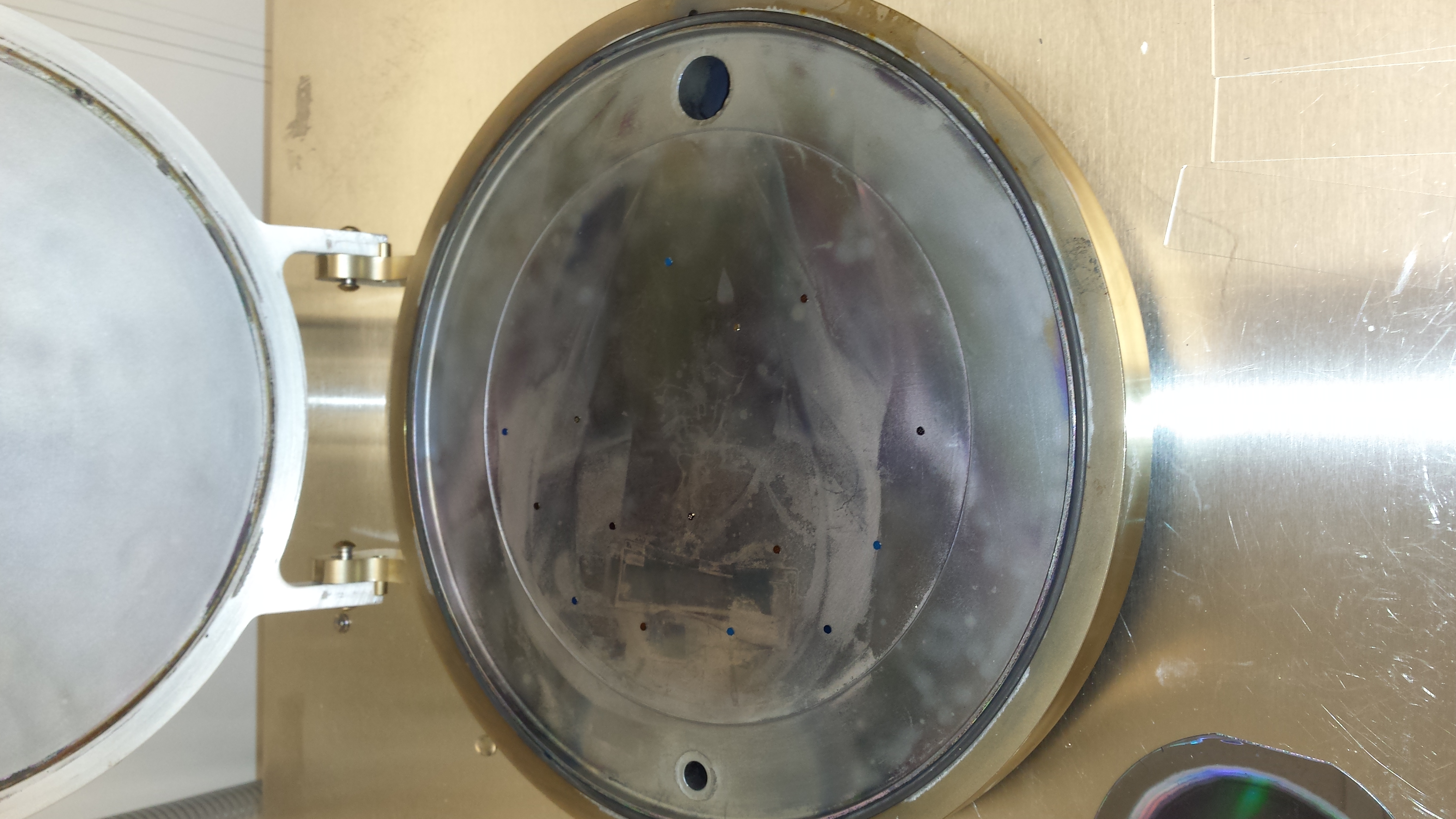
As you can see, the TEM grids in the center of the chamber are still displaced, but on the periphery they are relatively unmoved. This was the method I used for all of the ALD work for Jamie and JP (a forthcoming post).
Frustrated that even this apparent success means that most of the chamber can’t be used, I contacted Cambridge Nanotech (aldsupport@ultratech.com) and explained my problem. A technician got back to me promptly:
Karl,
One way you can solve or minimize this problem is with a 2 stage valve (Stop Valve). We have done some work using these in the Savannah and have had some pretty good success with smaller sample sizes. Unfortunately we cannot tell you if the solution will work perfectly for your sample sizes (3mm) since we have not experimented with every size, but it works pretty well on 5mm silicon samples.
The valve has almost the same form and fit as the current valve, but has an additional airline for the first stage (which is a 70um orifice). You should be able to “work” the airline in with the current heater jacket you have but we do offer the right jacket that has the proper hole for the hose. This stage is driven by a 24Vdc MAC valve and is run from an available port in the ebox. The software setup.ini file will have to be slightly modified (simple text file) and you will have to update your software to version 25.xx or higher.
TJ Ennion can quote you the option if you are interested. (cc:d on this mail)
I priced it out, and it would be $14,000 (Quote here) to upgrade.
I discussed this with Josh, and he had figured out another better trick that completely bypasses this issue entirely. There are two nitrogen feeds to the ALD (labelled 1 and 2 below):

Nitrogen feed 2 powers the actuators for the mass flow controller. Nitrogen feed 1 supplies the reaction chamber. Josh discovered that for whatever reason, when the system is vented to the air, there is a small amount of both nitrogen gas and vacuum in the chamber. You can therefore load your sample, press lightly on the chamber lid to seal it slightly, and turn off feed 1 to get the chamber to slowly begin a “pre-pump” cycle.
The labview software shows the pressure in the reaction chamber, and normally when the system is pumped down the pressure looks like this:
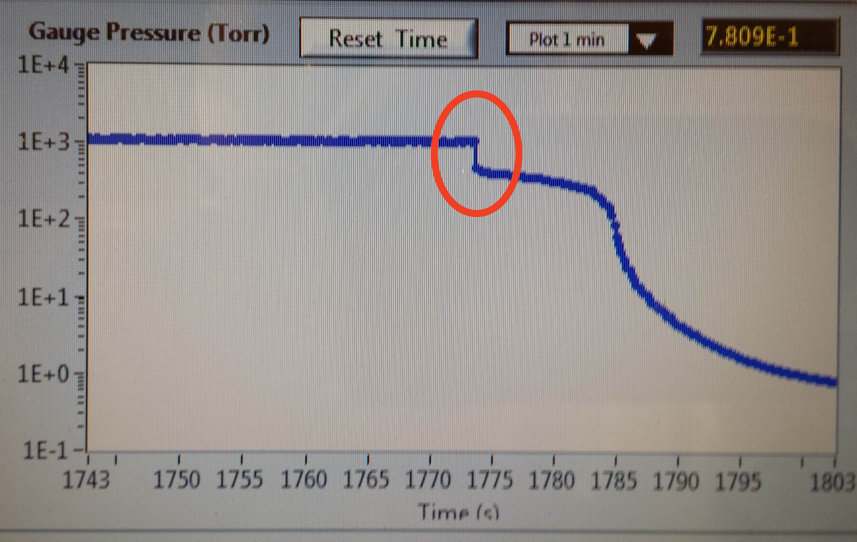
This circled orange area is where the lid is compressing downwards, and presumably is the moment when the chips fly everywhere.
If, before we begin, feed 1 is turned off, the flow looks like this:

(where the circled area is the moment when feed 1 is turned off), and if we wait for this pressure drop to stabilize before clicking pump on the labview interface, we get the following curve:
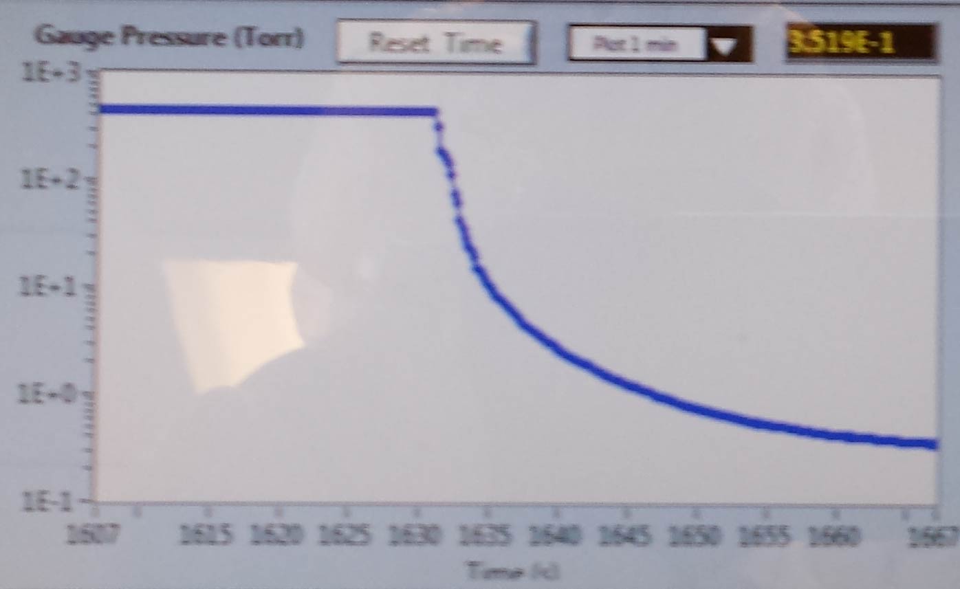
which is much smoother than the standard pumpdown. This is born out by my TEM grid method:


Note that once the pumpdown is complete, feed 1 must be turned on again.
To conclude: Josh’s technique of turning off feed 1 and allowing the system to be under partial vacuum before clicking pump works very well.