Spreading of HUVECs on Dimpled Sylgard-184 Substrates
To analyze the dimpled Sylgard substrates that we’ve been making, we’ve been conducting experiments to investigate how topographical differences in the surface of a substrate impacts HUVECs and ADSCs, in this case the dimples. We’ve already shown that cells will grow on these membranes in our “Dimpled Sylgard Membrane Device” post and that our substrates are wetting in our “Degassing Experiments” post, so now we’re characterizing spreading and proliferation. We can hypothesize that the dimples will encourage cellular spreading by giving the cells something to grasp as they spread across the surface. Shown below is a rendering of one of our PDMS devices which we used for all of the experiments.
 Not drawn to scale.
 The black represents a single well of a 24 well plate, in which our devices were situated.
The red represents our textured Sylgard membrane.
The green represents a PDMS retention ring to contain media for the cells on the membrane.
The blue represents a droplet of media and experimentally, the device could hold a~25uL droplet.
The retention ring was a major design parameter for these devices being the location where our cells would be deposited and all of our media contained through the first hours of the experiment. From the experience I had, the oval wets easily because you can form a small droplet on the tip of the pipette and then touch it down on the gasket without interfering with the substrate or the cells on it. The circular retention ring was chosen because it maximized the area for ozone adhesion to the plate while still maximizing ease of placement in the wells. The inner oval was 9.5mm^2 and contained up to 25uL of fluid in preliminary tests. The shape of the final retention ring is shown below:
 Not drawn to scale.
Two plates were constructed and each condition was duplicated on each plate making each condition quadrupled. This ensured that we had at least two wells to use for data acquisition. By quadrupling each condition we could combat the delmaination of the substrates or if one of them was upside down, issues which arose during this experiment. The condions were as follows:
-TCP control
-100um un-thinned Sylguard
-100um Sylguard thinned with 33% cyclohexane
-3um dimpled Sylgard
-3um dimpled Sylgard thinned with 33% cyclohexane
-8um dimpled Sylgard
-8um dimpled Sylgard thinned with 33% cyclohexane
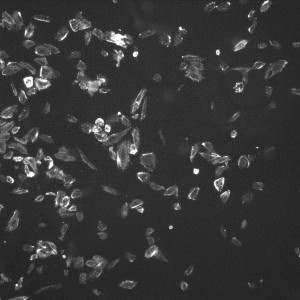
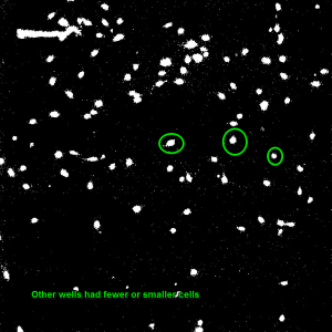
To construct these devices, the PDMS retention rings were cut using Silhouette Studio and a Silhouette Cameo craft cutter and the rings were cut out of a 100um PDMS sheet. Once the rings were cut, they were cleaned by spraying them with 70% Ethanol and dried by gently dragging them across a sheet of lens paper. The substrates were cut out with a razor blade at a size appropriate to the gasket (~4.5mm x 4.5mm) and cleaned in the same fashion. To adhere the two together, each face was treated with ozone from a corona wand for a minute using the wire attachment. The faces were then gently pressed together making sure to line up the 4mm^2 window containing the dimples with the inner oval and any wrinkles or bubbles were gently smoothed with forceps. To put the devices into the wells, each well was ozone treated with the corona wand point source for 20 and the bottom of the gaskets were treated with the coronal wand wire attachment for one minute. The apparatus was then placed in the well and wrinkles and bubbles were removed with forceps. The wells were then seeded with p6 HUVECs at 125 cells/mm^2 and the wells were flooded with media after one hour. After 24 hours, the cells were fixed using 3.7% formaldahyde and stained using DAPI and Phalloidin. Four images were taken of each well (one in each corner of the 4mm^2 membrane to cover the entire window) using the phase, DAPI and GFP settings on the microscope. Below and to the left is an example of one of the GFP images of a 8um dimpled substrate. GFP allows us to see the Phalloidin F-Actin stain. To the right of that picture is an example of an image of HUVECs on 3um dimples once the threshold has been adjusted. For comparison, the image below those is an image of a unthinned Sylgard-184 well after the threshold had been adjusted.
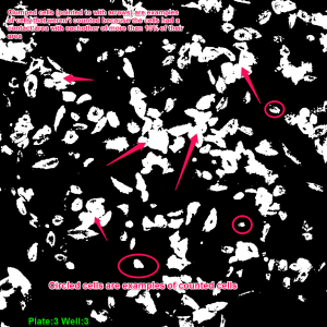
The images were analyzed in image-J by smoothing them, adjusting the threshold slider to ensure clarity, and measuring the area of each cell which had no more than 10% of it’s area in contact with another cell. The count given by image J is in pixels and to convert to millimeters squared, a conversion factor of 1.2769 (times the number of pixels) was used. The cells were counted and their size was put into a Microsoft Excel spreadsheet. The bottom 25% of the data was removed to ensure that debris or dead cells weren’t counted. The box plot from the top 75% of our data is shown below along with averages from the data.

One thing that our data consistently shows is that the pores do seem to increase cell spreading possibly because they give the cells something to grab onto.
Another observation is that the cyclohexane diluted substrates didn’t encourage cell spreading and that could be due to the reduced stiffness (we think), cyclohexane’s impacts on surface properties of the material, or the possible toxicity of any cyclohexane that has remained in the Sylgard. It would be interesting to do a contact angle experiment with cyclohexane diluted PDMS and compare it to the other substrates.
From the box plot, we can see interesting differences in our data as far as each substrate goes and it appears that both dimples and thinning the substrates with cyclohexane impact the spreading of HUVECs. More to follow with different stiffness substrates as well as substrates with different surface topographies.