Microarray Summary
Some background and a quick summation since I have done a great job at avoiding posting.
My undergrad background before the lab
- Chemistry, physics, math (minor) and a random psychology minor
- biology
- I questionably knew what a cell was
Overarching theme
- Putting a microarray on top of the membranes for cell culturing
- Currently cells are basically in a low security prison, they can move around and interact with other cellmates all the while surrounded by a huge a silicon wall on the outer edges. Microarray is equivalent to a high security prison, cells can possibly be allowed to talk and they get fed.
- Allows for culturing on a smaller scale. Due to the thinness of the membrane cells can all be fed at once instead of 1 at a time (bioreactor)
The Gabroski lab has previously made microarray’s on and off the SiO2 membranes.
- polyethylene glycol diacrylate (PEGDA) has minimal cell adhesion
- polyethylene glycol diacrylate combined with a photo initiator and UV light (360nm range) triggers a reaction that turns the liquid polymer from a liquid to a solid. A photomask with the desired pattern is used to block light from reaching certain areas.
- Previously done using the UV channel on a microscope.
- good start but not a perfect system
- More on this in a future post detailing a collaboration with another group at RIT
- polyethylene glycol diacrylate combined with a photo initiator and UV light (360nm range) triggers a reaction that turns the liquid polymer from a liquid to a solid. A photomask with the desired pattern is used to block light from reaching certain areas.
- More then a few failed systems before shifting to surface coating SU-8
Current work-Surface coat SU-8
SU-8 is a common cleanroom mixture that among other things is used in the Lift-off process. Modifying its surface is a common practice. For our purposes we want to decrease cell adhesion (figure ).
A group lead by Dr. Allbritton devised a simple but effective means of modifying the surface.
- Unreacted SU-8 is comprised of 3 things. a solvent, phototacid generator (PAG) and the SU-8 molecule.
- In short UV light triggers a complex reaction starting with the PAG which forms a number of various by products. A heating step (PEB) then allows the products to react with the SU-8 molecule forming a complex solid structure.
- Not all of the PAG is used up and 1 of the by products happens to allow the possibility of attaching certain polymers to the surface through the use of a 2nd UV exposure later on.
Why PEGDA?
- The random shot in the dark worked. A random junk section of lifted off SU-8 grid was tried on the closest thing we had in the lab to any of the compounds in the Allibritton paper in terms of how the reaction proceeds. I didn’t expect it to work as well as it did.
- In some ways it worked too well.
- If the need arises the compound is easily available in a number of molecular weights.
- PEG and its derivatives are commonly the go to choice for a variety of biomedical applications
- The polymer is transparent
Current experiments can be summed up with having the goal of finding that magic point at which the surface of the SU-8 array is covered with a 5-500nm coating while at the same time not covering the membrane, along with quantifying the effects of various changes.
Factors to consider
- various ratios of PBS and PEGDA
- Energy output needed to trigger PAG in second exposure.
- Depending on the settings somewhere between 900-1700 mJ for noticeable formation on a flat sheet without ozoning
- with SEM and AFM data this value will likely drop
- how different SU-8 settings affect this
- Amount as well as intensity need to be considered
- mixed results, more data points needed
- Depending on the settings somewhere between 900-1700 mJ for noticeable formation on a flat sheet without ozoning
- effects of oxygen on the reaction
- PEGDA is affected by oxygen inhibition
- Placing PEGDA in a vacuum pump is enough to make significant differences in the energy needed. More precise measurements need to be made but it somewhere between 25-50% less
- ozoning the surface of SU-8
- needed to drastically decrease SU-8 hydrophobicity
- complicated issue
Optical microscope image of PEGDA on SU-8 after washing away unreacted.
- Control photos of a fresh SU-8 coating is flat and smooth with few defects that show up.
And I didn’t realize tiff’s don’t work,
insert later
Optical microscope image of PEGDA on ozone’d SU-8 (far from ideal coating, looks rough even at eye level).
insert later
Su-8 coating settings for 3010 model.
3 main classes of settings are used and ranked in order from most to least likely to trigger a surface reaction.
Allibritton- ideally settings used by Allbritton group.
- Allbritton used SU-8 model 10 instead of 3010 so some rough conversions are made. The same chemicals are in both mixture.
Bob-middle ground settings fine tuned by Bob carter for the lift off process. Uses parameters from the manufacturer’s suggested settings
Ramped up- attempt at stopping surface reaction
The first few attempts with just flat sheets showed no significant differences. Allbritton settings contained an error in the UV dose which likely left it too close to the Bob settings. The ramped up settings were my attempt at stopping the reaction at the surface. Rethinking the process lead me to believe that I pushed one of 2 key parameters in the intended direction and the other in the wrong. Further research lead me to believe I hadn’t pushed things to a far enough extreme. More importantly I found papers that pushed the settings way past the manufacturer recommended, allowed me to proceed without worrying about a safety issue. Results will be known once a 16 hr bake at 160-180C on a hotplate is finished, nature of this means it will take multiple days. The longer and hotter bake time should decrease the amount of Su-8 monomer remaining in the system thereby giving the PAG fewer things to interact with during the 2nd UV step. The less defined edges in figure 2 vs figure 1 are likely a result of the longer PEB allowing some reaction of SU8 monomer outside what was exposed to UV.
Stack is Silicon on bottom followed by silicon oxide with the SU-8 microarray on top.
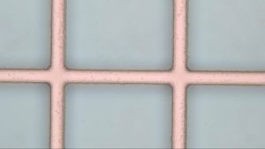
Allbritton settings (Figure 1)
- 10 um wide lines
Allbritton-David Modified (Figure 2 )
- Every step was the same except for the PEB. This one is 10 minutes instead of 3 and takes place at 150C instead of the standard 95C
- Currently on 16 hr bake that took place after the development step.
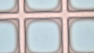
Both settings showed a cloudiness that may be due to needing a longer wash step this along with the longer bake time may have contributed to less well defined edges in figure 2.
Cell culturing attempt 1 done by Stephanie
- My presence seems to have a negative affect
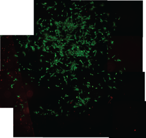
- ADSC’s On TCP, red=dead, green= alive
- Viability is 95-100%, 75% of the theoretical amount of cells didn’t even attach
Cell culturing control attempt 2
- It went as expected
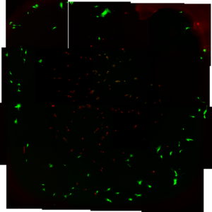
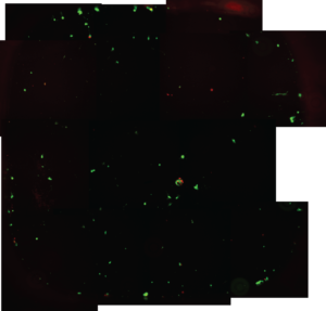
Green cells= Alive
Red cells= Dead
Cell viability on 4 different surfaces was measured, TCP (tissue culture polystyrene),SU-8, 100% PEGDA, and PEGDA (25%) mixed with PBS. TCP looks as expected, high coverage and 90%+ alive. Su8 has 20-30% of the cells tcp has, su8 showed a similar number of dead cells. PEGDA (25% and 100%) showed as expected, very few if any of the cells attached.
Basic statistics that sum up the results
| Live | Dead | Ratio Live to Dead | % Live | Exp Total/Theoretical Total | % su8 total/tcp total | % su8 live/tcp live | % su8 dead/tcp dead | Total cells | % Dead | ||
| TCP-1 | 586 | 48 | 12.20833333 | 92.42902208 | 0.7925 | 634 | 7.570977918 | ||||
| TCP-2 | 717 | 63 | 11.38095238 | 91.92307692 | 0.975 | 780 | 8.076923077 | ||||
| SU8-1 | 192 | 49 | 3.918367347 | 79.66804979 | 0.30125 | 34.08769448 | 29.4704528 | 88.28828829 | 241 | 20.33195021 | |
| SU8-2 | 121 | 34 | 3.558823529 | 78.06451613 | 0.19375 | 21.92362093 | 18.57252494 | 61.26126126 | 155 | 21.93548387 | |
| PEG25-1 | 0-25 | 0 or close to | |||||||||
| PEG25-2 | 0-25 | 1 or close to | |||||||||
| PEG100-1 | 0-25 | 2 or close to | |||||||||
| PEG100-2 | 0-25 | 3 or close to | |||||||||
| scattered random rounded cells on pegda, some possible artifcats | |||||||||||
| pegda25 appearsd to have fewer then 100 | |||||||||||
TCP (Figure 3)
SU-8 (Figure 4)
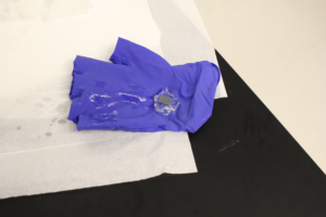
Figures 5 and 6, proof that the PEGDA layer can be extended far from the surface
- Dr. Gaborski thought this was cool
Figure 5
- Clear case with an SU-8 wafer piece at the bottom and filled with PEGDA. This is after dumping a lot of UV energy into the system.
- pipet tip to show it is solid
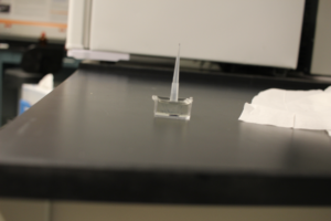
Figure 6
- Same sample from figure 5 but upside down and out of the case
- 10mm height and 12 mm from the furthest point of the the SU-8 Surface
- reaction reached the top
- 10mm height and 12 mm from the furthest point of the the SU-8 Surface