Physiological Facade: Fibronectin coating membranes in an attempt to improve the performance of Staphylococcus aureus propagation assays using the µSiM
Parallel with my efforts in the Osteomyelitis project to coat our membranes with polyurethane acrylate, I began working with the Gill lab on improving the performance of our uSiM platform as a propagation assay for Staphylococcus aureus. In the past we have gotten a lot of good data using this assay, but its performance has been inconsistent (<50%). This has been no different for our most recent attempts where we have not had greater than 40% success rate in our positive wild-type controls (S. aureus strain, USA300). In an attempt to increase the performance of our assay I will detail our most recent approach which involves coating the membrane with fibronectin (FN).
Fibronectin as a physiological coating
Fibronectin is an extracellular matrix protein found throughout the human body. S. aureus and many other cell types are known bind to FN. Within our lab, several McGrath lab members utilize FN coatings to promote cell adhesion and monolayer formation on our membranes. In a similar fashion, we looked to use FN to promote adhesion of S. aureus to our membrane in hopes that it would increase the success rate (S. aureus getting through our membrane) of our propagation assays. To coat the membranes, we modified the FN coating protocol used by those who do cell culture in our lab, described below.
Fibronectin coating protocol*
Differences from the established coating protocol for NPN written in red
uSiM device assembly
– UV all components, chips, tweezers, and storage containers for 15 minutes in a cell culture hood
– Assemble components
– Pre-wet bottom channel with Tryptic Soy Broth (TSB) until completely wet (indicated by fluid protruding from the port opposite the injection port)
– Add sticker (double-sided adhesive tape cut to fit the uSiM width) to block one port of the device
– Fill well with 100 uL of TSB
– Inject 40 uL of TSB to test if the pores are open (enters well with little to no resistance)
– If there is a large amount of resistance (indicating the pores are not open), discard the device and build or use another
– Remove all liquid well volume (~140 uL)
Diluting Fibronectin
– Diluted 1800 µg/mL stock Fibronectin
– For this application, Fibronectin needs to coat the surface at a density of 5 µg/cm^2
– Aline device surface area = 0.37 cm^2
– 1800 µg/mL * V1 = 18.5 ug/mL * 1.6 mL
– V1 = 0.016 mL = 16.44uL of FN stock solution into 1583.6 uL of 1X PBS
Coating
– Put 100 µL of Fibronectin coating solution into Aline wells, coat for 1 hour at room temp in sterile conditions
– Remove coating solution after 1 hour, and replace with 1x PBS
– Store wet (1x PBS) and cold (2-8 deg C)
– Stable for up to one week
*Each step was done in a sterile environment
Propagation Results
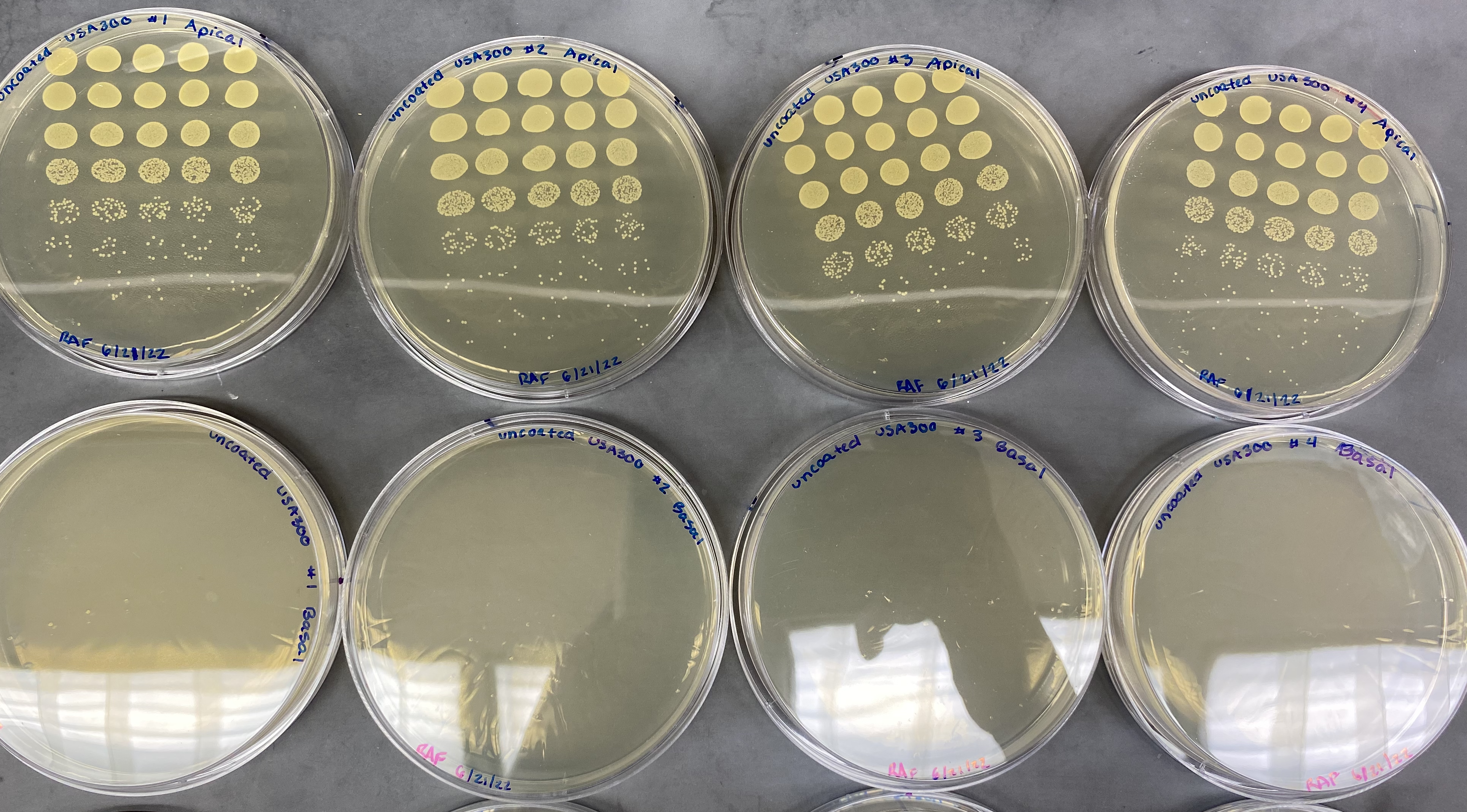
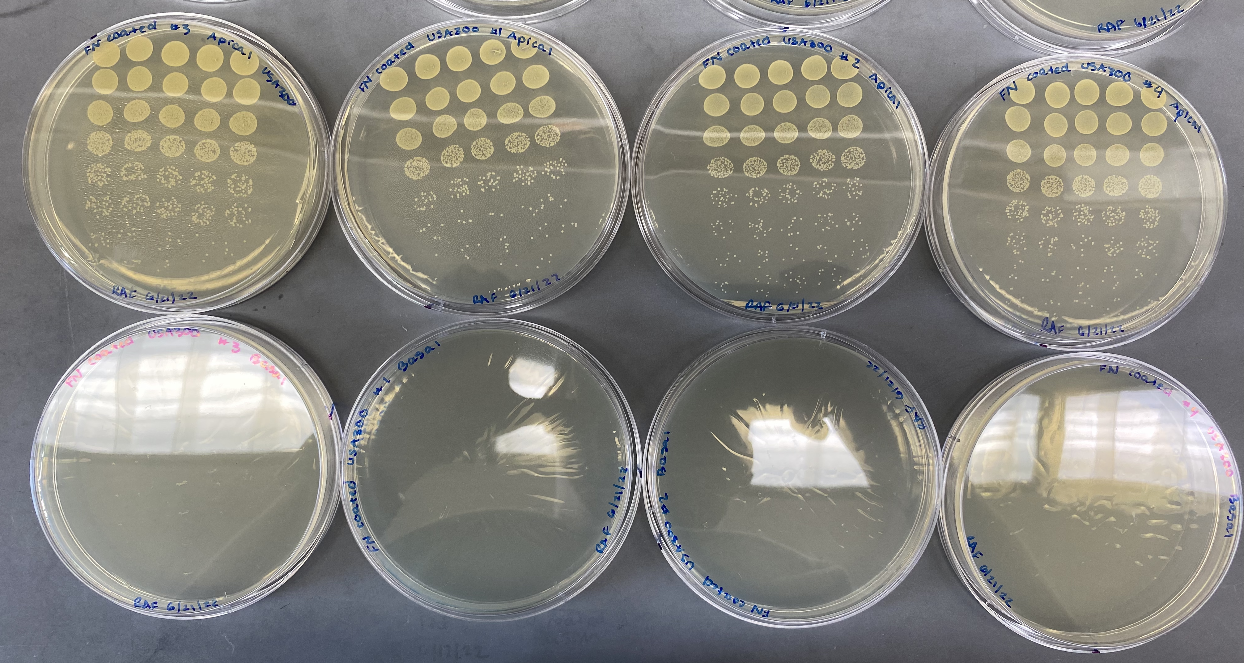
Currently we are gauging propagation results by counting colony forming units (CFUs). Bacteria suspended in tryptic soy broth is injected into the well and is allowed to divide for 6 hours. Sample is taken from the well and the bottom channel, diluted, and plated separately overnight. The well sample represents the apical side and the bottom channel sample represents the basal side.
Uncoated chips
Following the trend we have seen up until this point, devices which contained uncoated chips did not have any bacteria in their bottom channels. USA300 should be a positive control for an uncoated membrane, so we should see bacteria in the bottom channel. This highlights our continued struggle to get the assay to function properly.
Fibronectin coated chips
Unfortunately, similar results were seen in our uSiM devices which contained FN coated chips. Seeing no bacteria in the bottom channel of any of our devices, we decided to make sure that our FN coating was not blocking the pores of our membranes.
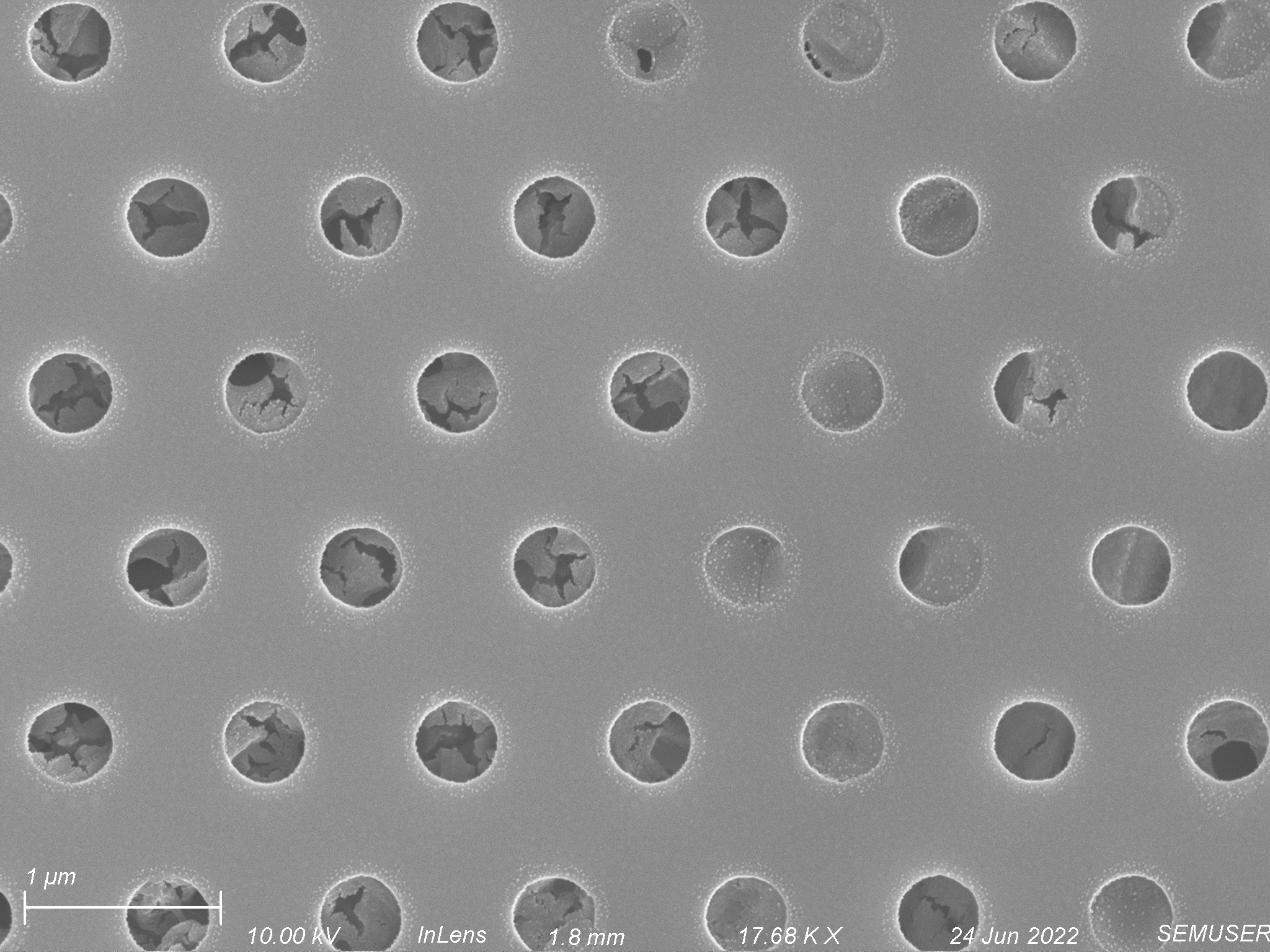
SEM Images of Fibronectin Coated 0.5 um Microporous Membranes
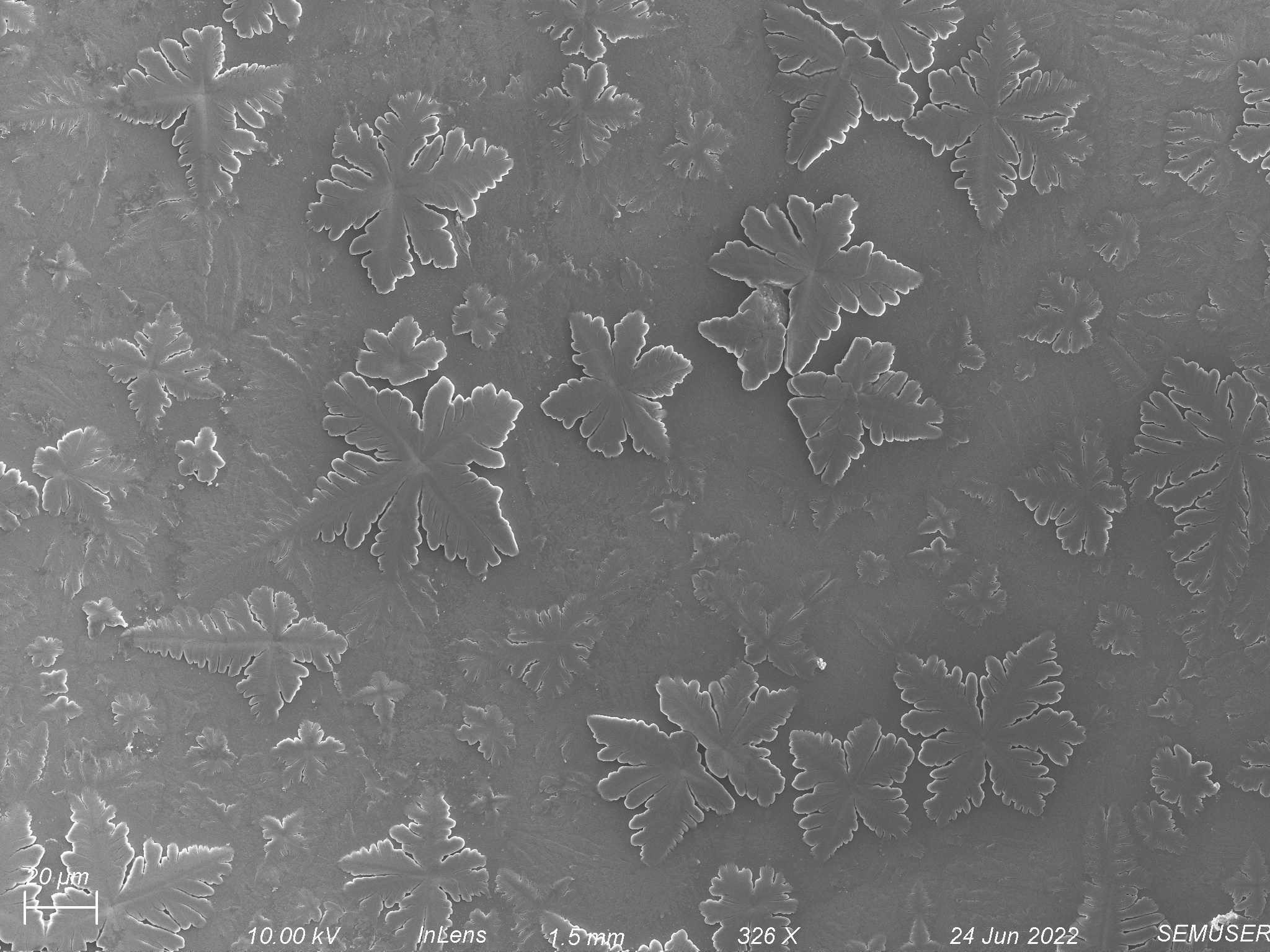
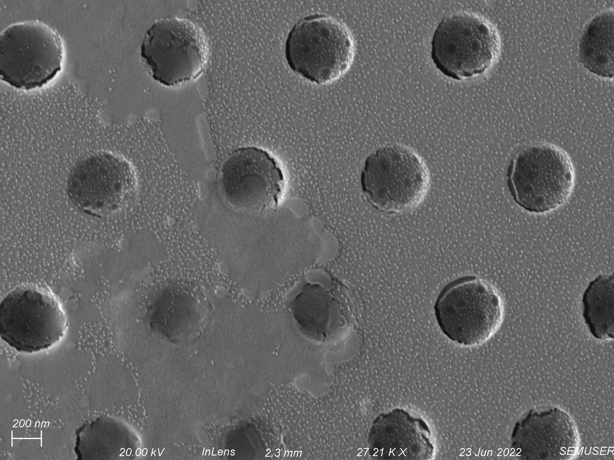
Membranes have to be dried before imaging on the SEM. This means that what we see in our SEM images may not be exactly representative of what things looked like when the environment was wet. It also means that since the devices are last wet with PBS, crystals from the salts within PBS are often seen within our images. An example of what these might look like is shown below.
Fibronectin coating in the of Tryptic Soy Broth
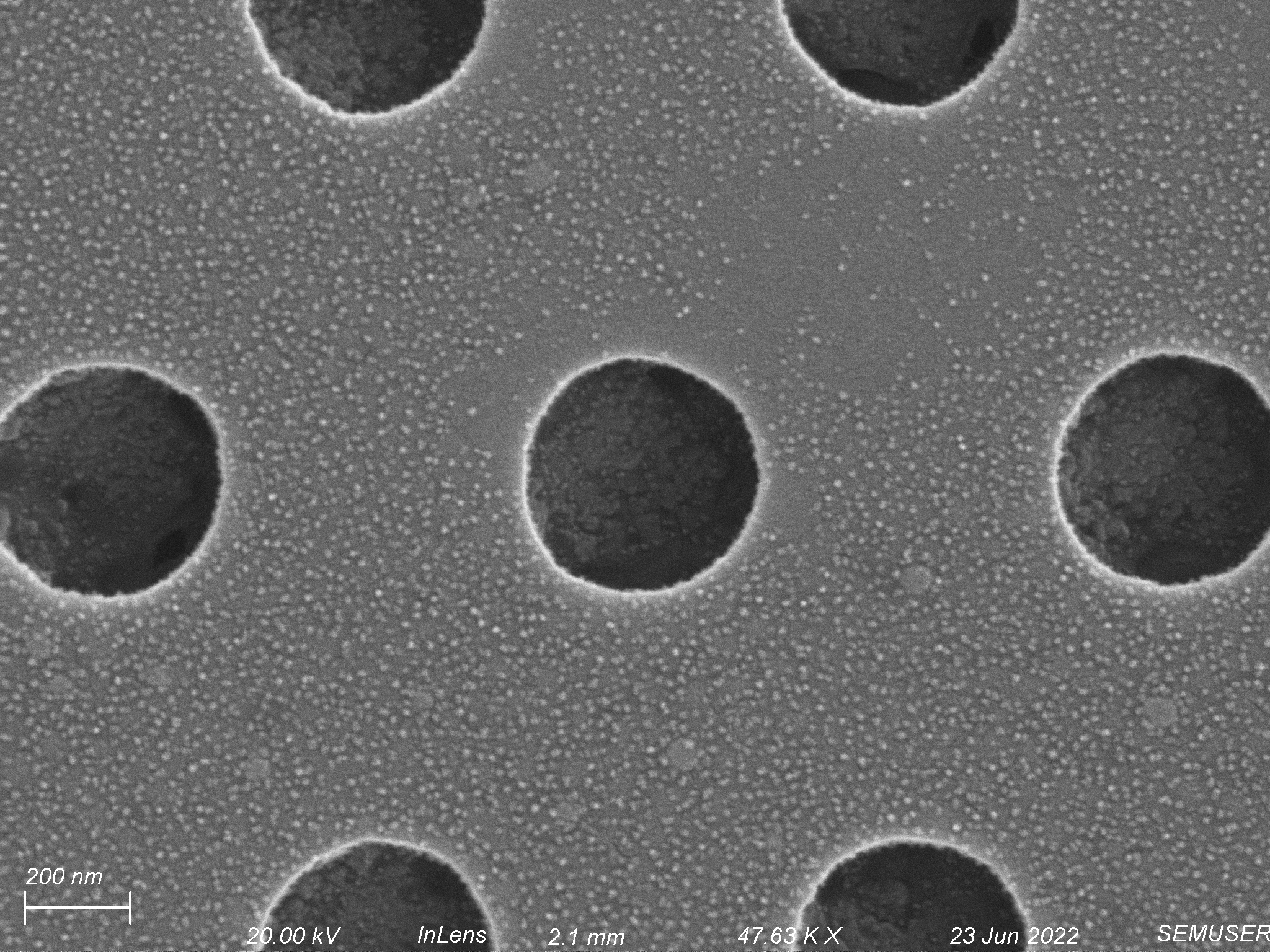
We first looked at a chip which we had coated for the experiment above. Since we had coated the chip with FN in the presence of TSB, we thought there might have been an interaction between the proteins of the TSB mixture and the FN which could have blocked the pores. We saw a wide range of pore states, shown below.

Fibronectin coating without Tryptic Soy Broth
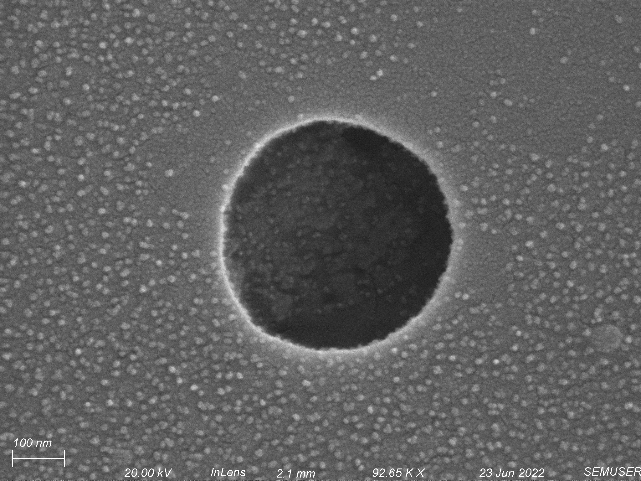
Unsure if the pore occlusion and constriction was due to an interaction between FN and TSB, I coated a membrane with FN without using TSB to wet the device beforehand. Interestingly, we saw similar pore occlusion and constriction which is shown below.

Conclusions
Instead of helping us, it seems all FN coating the membrane did was hurt us. By constricting or occluding pores within the membrane, we did not increase the performance of our assay. With this being said, it is hard to say what the FN coating looked like while the chips were still wet. We have thought of several different ways to move forward from this.
To see what the FN coating looks like while still wet, we may retry coating our membranes with fluorescent FN. This would allow us to image the membranes while still wet using the confocal microscope.
Talking with the Gill lab, we have also decided it is not necessary to pre-wet the devices with TSB. This would allow us to follow the traditional lab protocol where everything is done with PBS. If interaction between FN and TSB proteins is our issue, this should mitigate it.
The Gill lab also thinks aggregation of S. aureus may be giving us problems. They will test this hypothesis by sonicating S. aureus and seeing if aggregation is reduced.
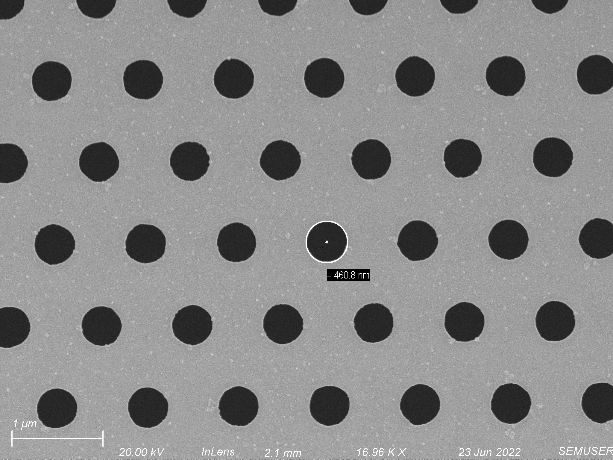
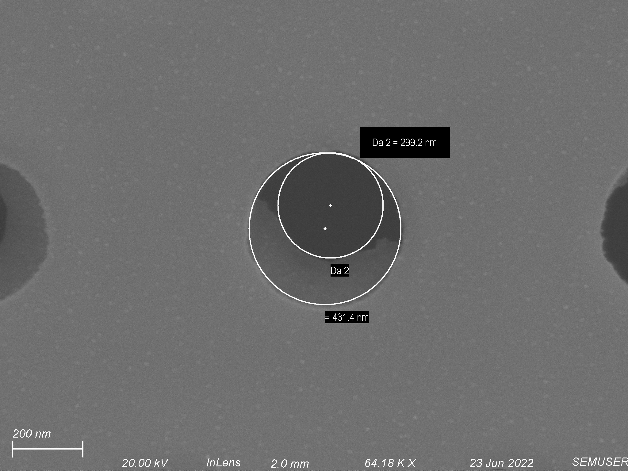
Another hypothesis is that S. aureus can only divide through pores that are at or larger than 500 nm in diameter. Lately the membranes we have been using seem to have pore diameters less than 500 nm (shown below). To test this hypothesis, I will increase the diameter of the pores on some membranes to ~600 nm and see if this has an effect on the success rate of our propagation assay.
Overall, while our first FN approach did not work we have many ideas with which we can move forward.