The Base of TraCe: Exploring the Fundamentals of the Etaluma Microscope
For year one of the Trace grant, I will be focusing on the development of a standard operating procedure for the uSiM-CA. To begin this process, I am transferring all of my current operating procedures from the Andor dragonfly confocal scope to the new Etaluma microscope. The Etaluma scope will be automated, collecting images of each device in an arrayed system. Images will be taken in the bottom channel and potentially also just below the membrane. This will image any bacteria that have transmitted through the membrane and gotten either just beneath it or down into the bottom channel of the uSiM-CA. While the Etaluma brings numerous advantages which we will utilize throughout our TraCe work, one downside is that it does not have confocal capabilities. The first problem we anticipate from this is that a widefield microscope will pick up too much fluorescence background from the bacteria sitting in the well of the device to clearly see the bacteria beneath the membrane and in the bottom channel of the device. Therefore, we developed a method to block the fluorescence of the fluorescent bacteria in the well by coating the underside of the membranes within each uSiM-CA with gold. For these proof-of-principle experiments, I will use fluorescent beads in lieu of fluorescent bacteria.
The Gold Coating Method
To decrease the transparency of the membranes, I coat what will be the underside of each membrane while in a uSiM-CA device with a defined amount of gold. Since I build devices with the membranes trench up, this means I coat the flat side of each membrane with gold. Coating is done with a denton sputter containing a gold target.
Imaging with the Andor Microscope
I tested three different gold coating thicknesses: 10 nm, 30 nm, and 50 nm. I compared all three of these thicknesses with an uncoated chip. Each membrane was imaged using the confocal and widefield modality on the Andor microscope. Figure 1 shows the images that I collected at the membrane.
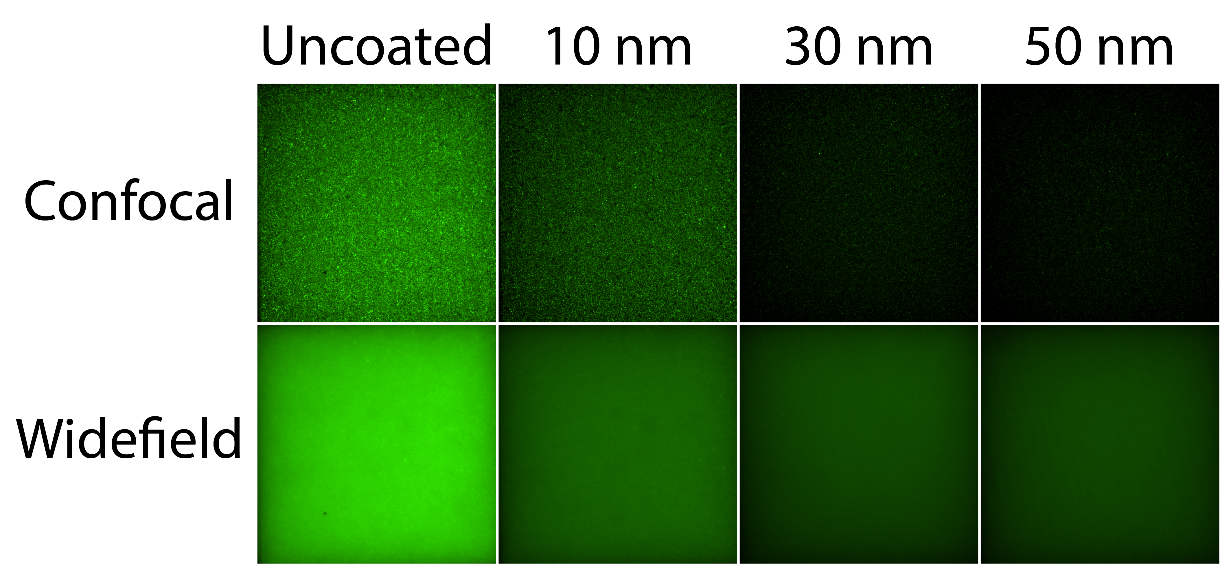
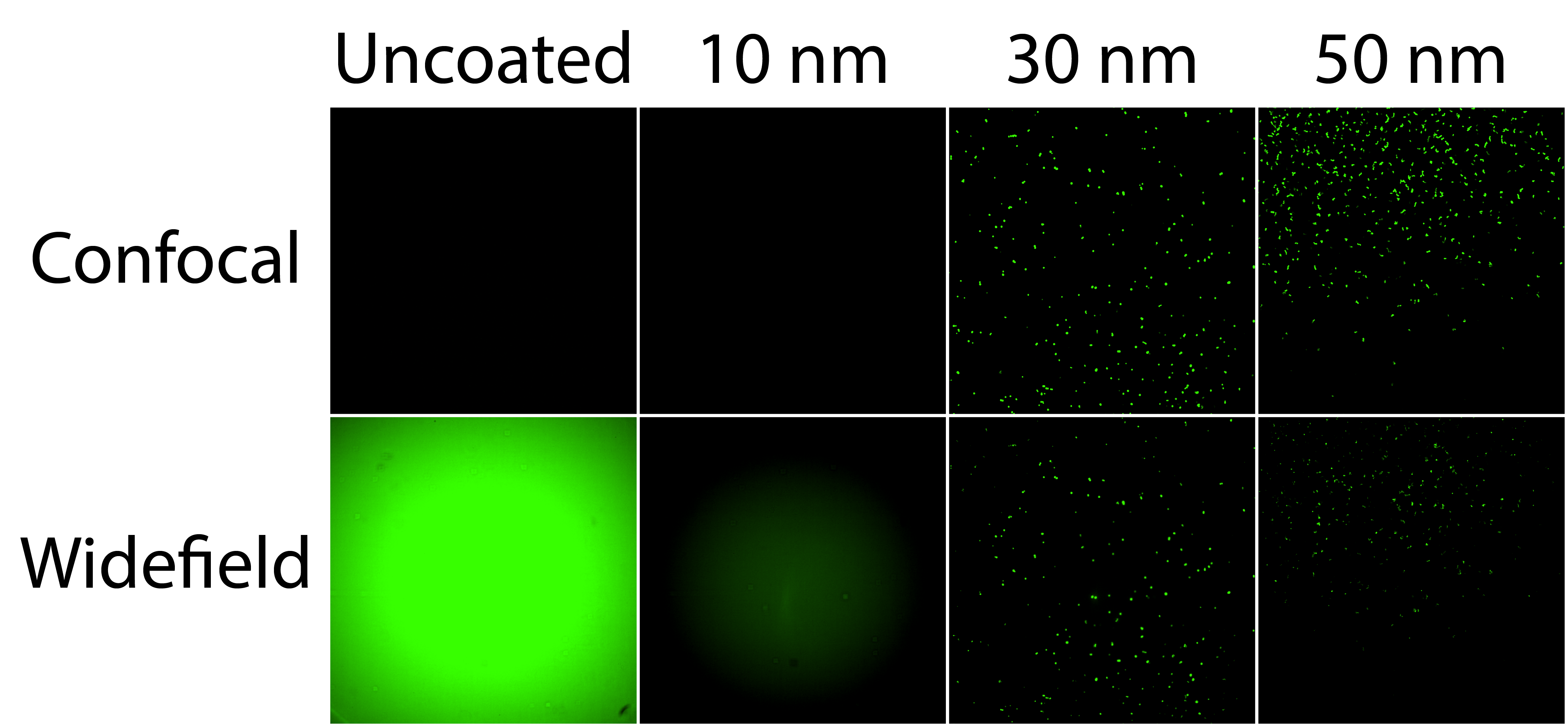
As expected, the confocal modality had much greater resolution. Nonetheless, fluorescent signal from the well did decrease as the gold coating thickness increased. Importantly, this trend carried over into the bottom channel which I imaged in the same manner, whose results are shown in Figure 2.
Imaging with the Etaluma Microscope
After receiving the Etaluma microscope and successfully decreasing the fluorescent signal from the well using gold coatings, I attempted the same experiment on the Etaluma microscope. Seeing as this was my first time using the scope, I also tested out the 4 different objectives which were installed into the scope.
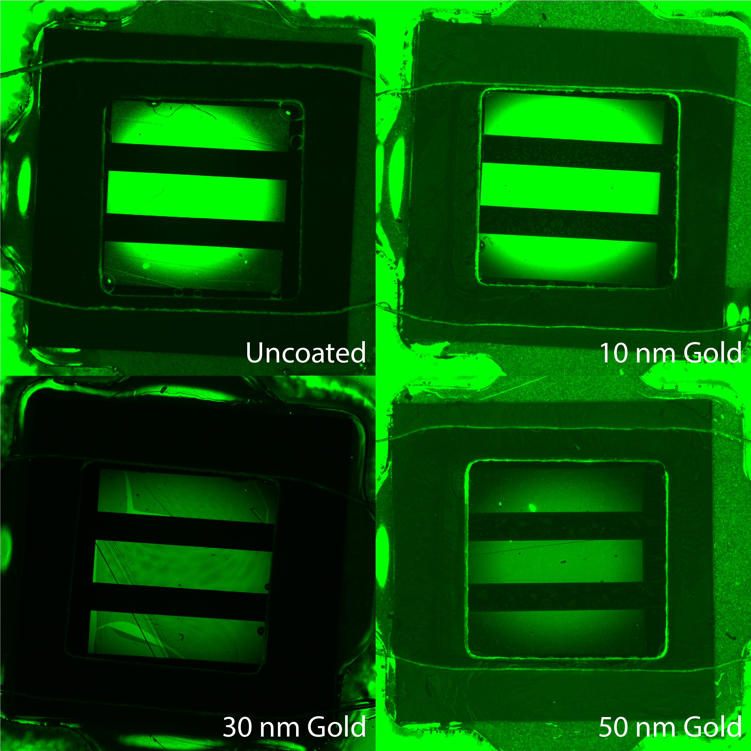
I began with the 2.5X objective and the same coating conditions (uncoated, 10 nm of gold, 30 nm of gold, and 50 nm of gold). While it was great to see the entire chip, the magnification was so low that signal from outside of the chip could be seen. This rendered the gold coating ineffective, shown in Figure 3.
Moving on from the 2.5X objective, I was able to get great images using the 4X, 20X and 40X objectives, shown in Figure 4 below.
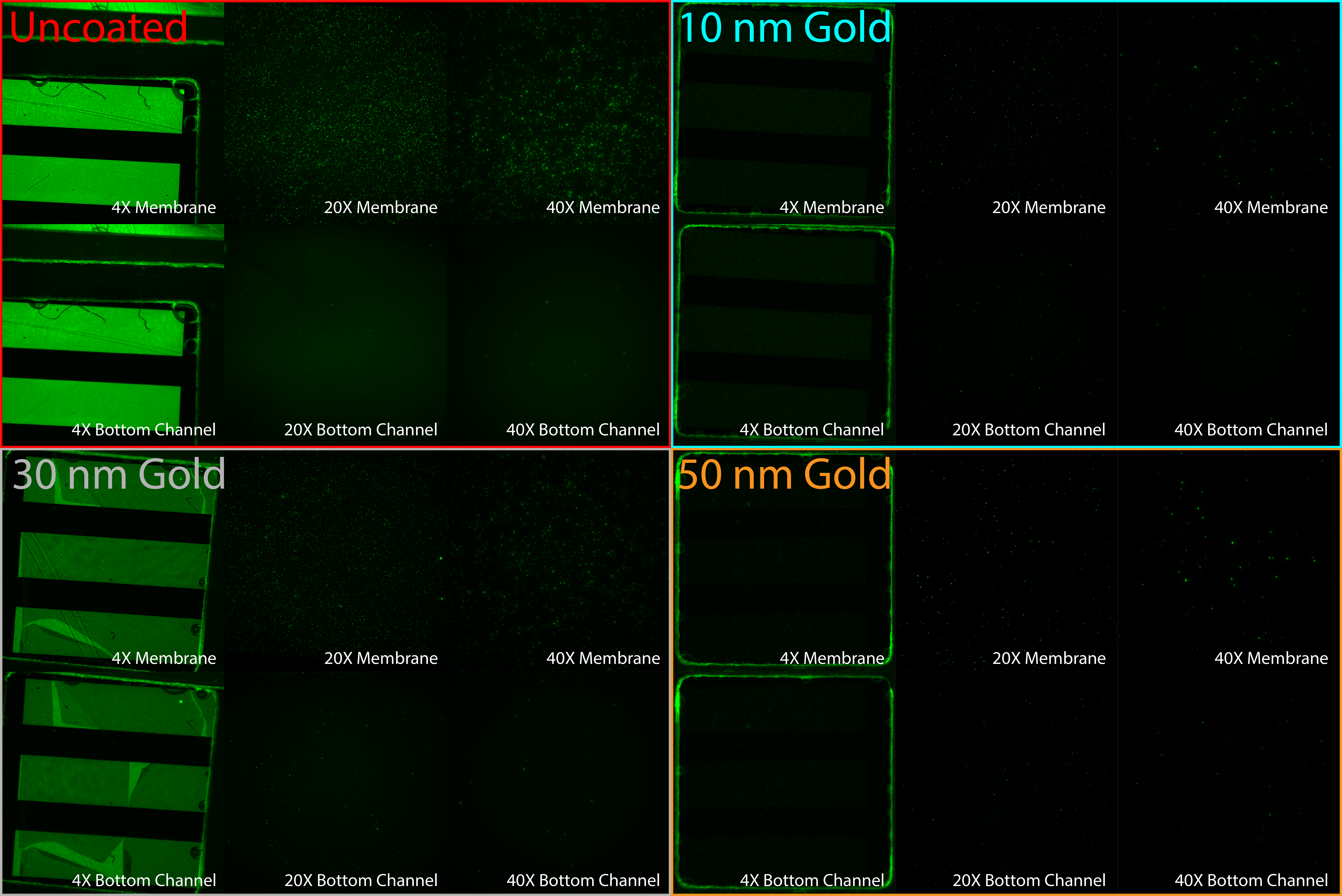
As seen on the Andor microscope, fluorescent signal from the well decreased as the gold coating thickness increased in both the bottom channel and at the membrane in images taken on the Etaluma microscope. To prove the point further, the 30 nm gold coated membrane broke during imaging to show a slightly elevated fluorescent background than the coating thickness trend would otherwise suggest.
Conclusions
Coating the membranes with gold to decrease fluorescent background signal from the well was a success. The extent of background elimination is directly proportional to the thickness of gold on the membrane. This will be a useful strategy moving forward if the signal to noise ratio is unwieldy in future work, but it is worth noting that the Etaluma seems to perform pretty decently without a coating. The 2.5X objective will be unusable for fluorescent imaging in future TraCe experiments, but the 4X, 20X, and 40X objectives seem like they could work great.
Your fluorescence emission bandwidth should be quoted here as thin gold is preferentially transmissive in the blue-green. Moving to a red-emitting fluorophore turns the gold into a mirror, something that could be considered if necessary.
If you’re concluding from these images the using consistent settings is most important. If you have dynamic range issues then try using the camera with a higher bit depth (12 bit rather than 8 bit RGB – even a Raspberry Pi camera can do this) and establish the settings under the conditions in which you get the highest signal in order to avoid saturation – you will then be able to quantitatively compare.