Measuring TEER for estimating barrier properties: to flow or not to flow?
I am trying to understand the development of endothelial barrier properties as the cells remodel under the influence of physiological shear stresses. I culture HUVECs inside my device on 100 micron thin type I collagen gel. I coat the gel with fibronectin on top to provide adhesion for the cells. It helps them to stay adhered under flow. I also polymerize same collagen gel under the membranes in the trenches as well. The basal gel act as ECM layer. I used wafer 1155 NPN membranes for this purpose. Eventually I will do it with microporous membranes, but for time being, I am using NPN due to the ease in working with them over microporous materials.
I assemble the device, incubate the media in apical and basal conditions for overnight. This step basically makes the collagen gels isotonic and make it as conductive as the media electrolyte. I record the resistance value before I seed the cells. This value is also referred as ‘background’ or ‘baseline’ resistance value. I will subtract this from all the further measurements. I seed the cells and let them grow till confluence before I start the flow. The setup looks like below.
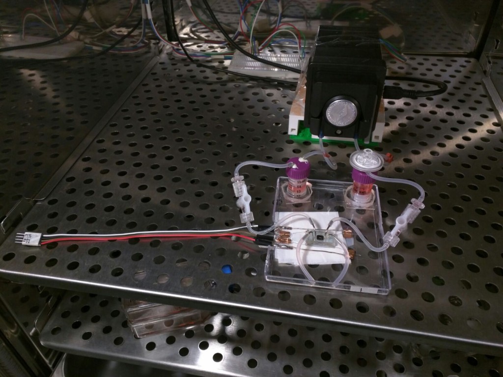
The 4 probe setup can be seen here. The pump is setup to flow the media from reservoir to the capacitor, and the capacitor reduces the pulsatile nature of the flow and generates the shear stress of 10 dynes/cm2 in the apical chamber where cells are growing. The EVOM meter to record resistance is kept outside the incubator.
Once cells get confluent, I start the flow and try to measure the flow twice a day. Now here is the tricky part: when I measure the TEER I am unsure whether I should keep the flow going or stop the flow for the measurements. The dilemma is shown here. The ions are subjected to convective flow, and electrical field in orthogonal directions. I am unsure of the magnitudes of each of the forces as of now, but the free body diagram explains it better. Theoretically, I should stop all kinds of convective flows and just let the ions respond to electrical field.
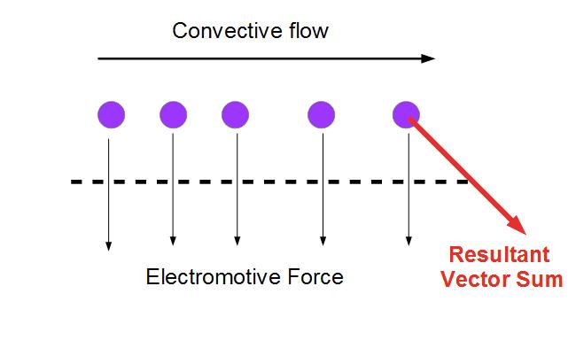
[I am yet to verify if this free body diagram is meaningful or not. Jim suspects that the EMF is far stronger than convective forces, implying the transmembrane diffusion will be significantly faster than convection. So theoretically it wouldn’t matter if flow is on or not. But I need to do the math behind this and verify.]
I decided to do both the ways. Once the flow was on, things get dynamic. Before every measurement, I used to stop the flow, and close the valves both upstream and downstream of the device. This used to mechanically isolate any fluid motion inside the apical side. The basal side was open to atmosphere. The TEER data looks like below.
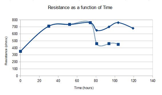
[SOLID = WITH FLOW; DASHED = WITHOUT FLOW]
The x axis is time and y axis is raw resistance. The background resistance, i.e. the resistance at t=0 is about 350 ohms which I have been getting consistently for last many experiments. I cultured the cells under static conditions for 3 days (74 hours), after which I hooked the device to the flow circuit at 10 dynes/cm2. The solid lines are the values that I obtain when I record TEER under flow, while dashed lines are the values I obtain under static. Till 74 hour timepoint, hence, both coincide, since there was no flow as such. After that the two curves deviate. Once I stop the flow, the values drop down to lower number, still above baseline though. But with flow ON, the values are higher, almost same range as the pre-flow value.
Serendipitously, I discovered that when I was stopping the flow, I was creating large vacuoles inside the device. The construction of my device is such that, once I close the valves connecting the apical chamber, I create low pressure zones inside, and the basal side is exposed to atmosphere creating high pressure zones. Not to mention, PDMS on the top and the tygon tubings are also gas permeable. So when I stop the floe and isolate the top chamber, there is a gas influx inside the chamber due to the pressure gradient that might create large vacuoles. See the movie below.
vid_20161122_210552 [ link to the movie; it downloads upon clicking ]
Movie – first the flow is on; then there is a blackout period- I stop the flow. We can see vacuoles appearing. Then I restart the flow causing another blackout. Vacuoles disappear after that.
Although the vacuoles can be confirmed, I am not sure why that can cause a drop in resistance by solid 200 ohms. Maybe the accumulation of gas causes the cells to ball-up and create loose gaps in junctional spaces. A very small hole or leak can create short circuit current and cause TEER to drop significantly. Either ways, it is necessary to prevent vacuoles from happening. Easiest way is to maintain the top chamber at 1 atm if not above. I plan to install 3 way valves, which will allow me to switch the device input from the reservoir to atmosphere and vice versa. This way, I will be able to maintain liquid-liquid interface at all times, and also prevent any pressure gradient inside the device. Both top and bottom chambers will be at 1 atm, so there should be no transmembrane flow of liquid or gas.
More to follow…