Dialysis Pressure Balancing
Background
For the in vitro portion of our dialysis project here at UR, we have settled on using two major experiments to test our devices for eventual transition to an in vivo model. These experiments include a single pass system using multiple syringe pumps to observe the effects of fouling on our membrane as well as a multipass system using parasitical pumps to probe our membranes for selectivity of cytochrome c and albumin. Our newest rotation student (Lindsay) and I have been focusing on the latter in recent weeks. One major issue Lindsay discovered is over the course of these 24 hour experiments, the fluid from one side of the device ends up completely filtrating into the other, leaving one side of the membrane completely dry. This issue could have occurred due to a variety of things, as the membrane manufacturing and pump system set up is not an exact science, but after a few weeks of troubleshooting we settled on the fact that this problem is most likely due to the incredibly high permeability of our membranes and the differences in pressures on either side of said membrane during our experiments. This pressure difference allows for a portion of the fluid to pass through the membrane during each pass, leading to the eventual draining of that side. NOTE: The top and bottom channels of the device differ in geometry, hence the variation in pressures at equal flow rates.
Experimental Design
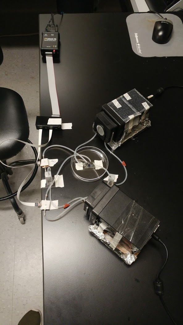
To test this hypothesis, I set up pressure sensors on either side of the bottom and top channels of our device and measured pressure drop across the membrane (Figure 1). I was also able to extract an average pressure from the data in hopes that I would be able to settle on two flow rates (one for the top channel and one for the bottom) that would balance out our pressures and allow us to continue with our experiments.
What We Found…
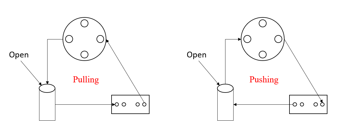
My (seemingly) obvious solution to this problem is to ramp up the flow rate on the top (since the fluid is pouring into the top channel) creating an increased pressure on the membrane from the top, eventually balancing out the pressures. However, I noticed by accident that when I increase the flow rate to maximum in the top channel, the issue is exacerbated. In other words, my assumption was totally wrong. This lead me to the realization that with our set up, we can have completely different fluid dynamics based on where we put our reservoir. If you place the reservoir before the device, the pump is pulling the fluid through the channel, and if you place the reservoir after the device, the pump is pushing the fluid through the channel (Figure 2). This subtle difference is key to our problem.
Results
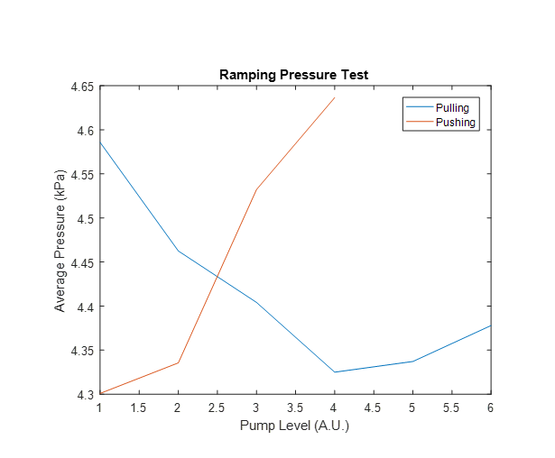
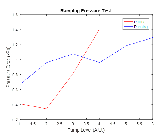
When in the pulling configuration, average pressure on the membrane drops as flow rate is increased (Figure 3). However, when in the pushing configuration, average pressure is increased as flow rate is increased (Figure 3). Nonetheless, the pressure drop across the channel still increases as flow rate increases in both cases (Figure 4). This difference in pressures and fluid exchange is all due to one thing: a reservoir that is open to atmosphere. The simple solution to our issue was to replace our reservoir with an air tight capacitor. This capacitor allows for pressure balancing (somewhat) and eliminates the ability of fluid exchange, no matter what configuration we use. Lindsay has been running the new set up over the weekend and to my knowledge we have not seen fluid exchange; the work continues.
In support of Alec’s conclusions, I have completed two runs without fluid exchange between the two sides.