Single Slot Inverted-Chip and Double Slot: Single-Pass Dialysis Devices
Introduction
In previous posts by both Alec and Kayli, the urea clearance performance of our bench-top single-pass dialysis devices has been described. Results regarding devices containing untreated, PEG-treated, and nonporous membranes can be found in the
“Current Dialysis Research [McGrath Lab, December 2017]”,
https://trace-bmps.org/current-dialysis-research-mcgrath-lab-november-2017/
and “Updated Dialysis Research” posts.
https://trace-bmps.org/updated-dialysis-research/
The nanomembranes present in these devices are manufactured on chips that present side specific geometry; as they contain a “trench” side and a “flat” side. Both sides of the membrane are exposed via etching processes, however, differences among these processes result in distinct surface characteristics and geometry (Figure 1).
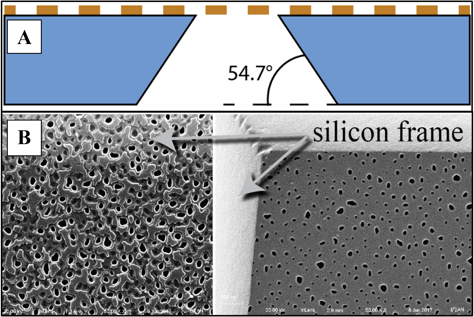
The trench side of the chip has previously been oriented towards the analyte (“blood”) channel within microfluidic devices with the justification that its geometry promotes fluid control and diffusion efficiency. In counterflow experiments, the trench ensures that the fluid is guided towards and contacts the membrane before exiting the channel. This approach aimed to mimic other dialysis devices that attempt to limit the volume of blood needed in similar experiments. Furthermore, the surface of the trench-side membrane is more size selective, offering beneficial filtering properties for an array of molecules. I intended to investigate this concept to determine if the trench side of the chip improved diffusion, more specifically urea clearance when exposed to the analyte versus dialysate channel in non-blood experiments.
Additionally, I began preliminary work with double slot devices under similar experimental conditions. My goal was to determine the relative urea clearance efficiency with respect to the previous single slot membrane standard using combinations of analyte/dialysate flow rates. In both sets of experiments, NPN membranes of 75 nm thickness were used.
Methods
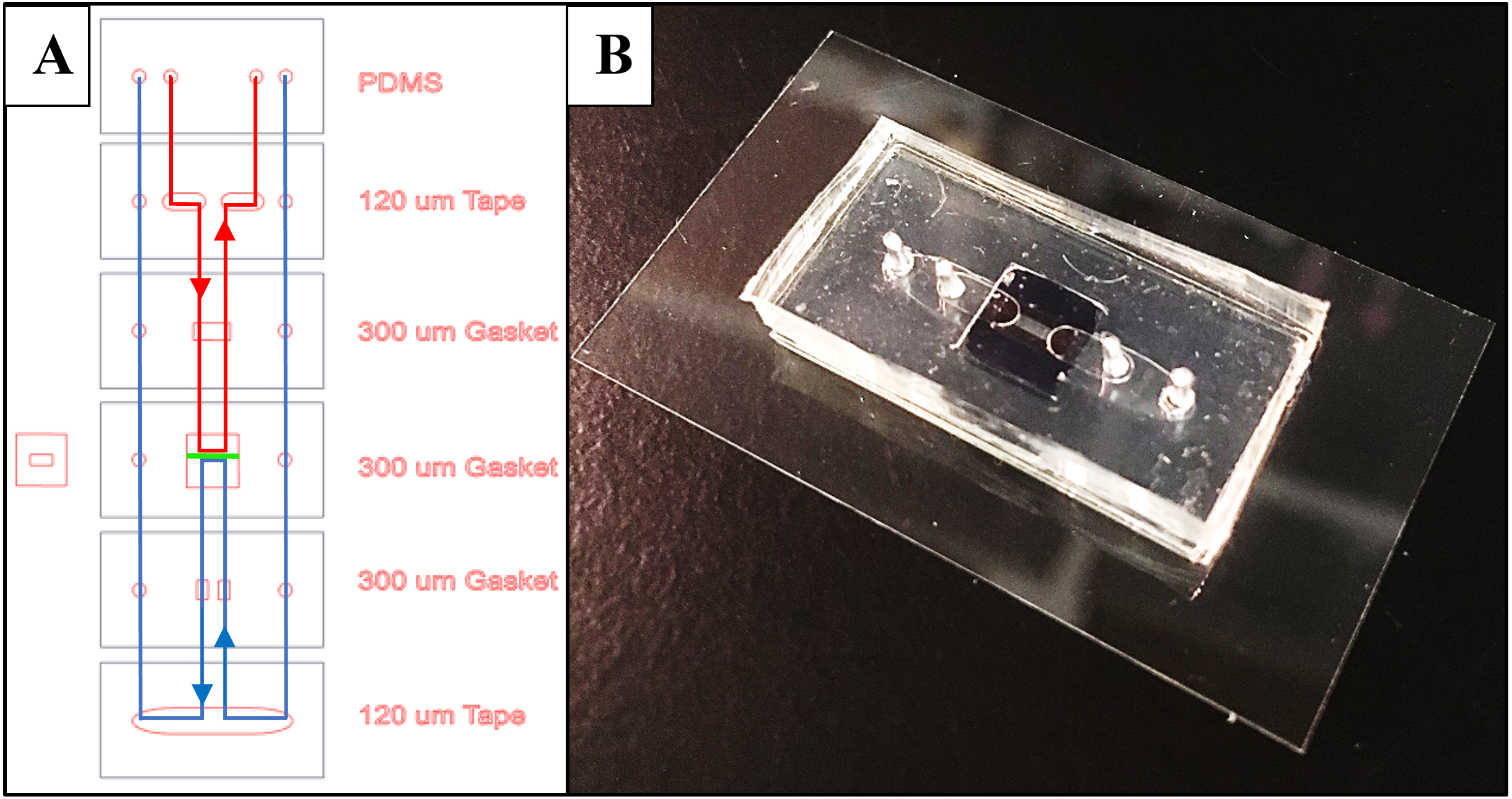
The original single slot single-pass devices were modified slightly to obtain a configuration that suited an inverted chip. Top and bottom sealing layers were interchanged to maintain contact between trench/flat sides of the chip and their respective gasket layers (Figure 2).
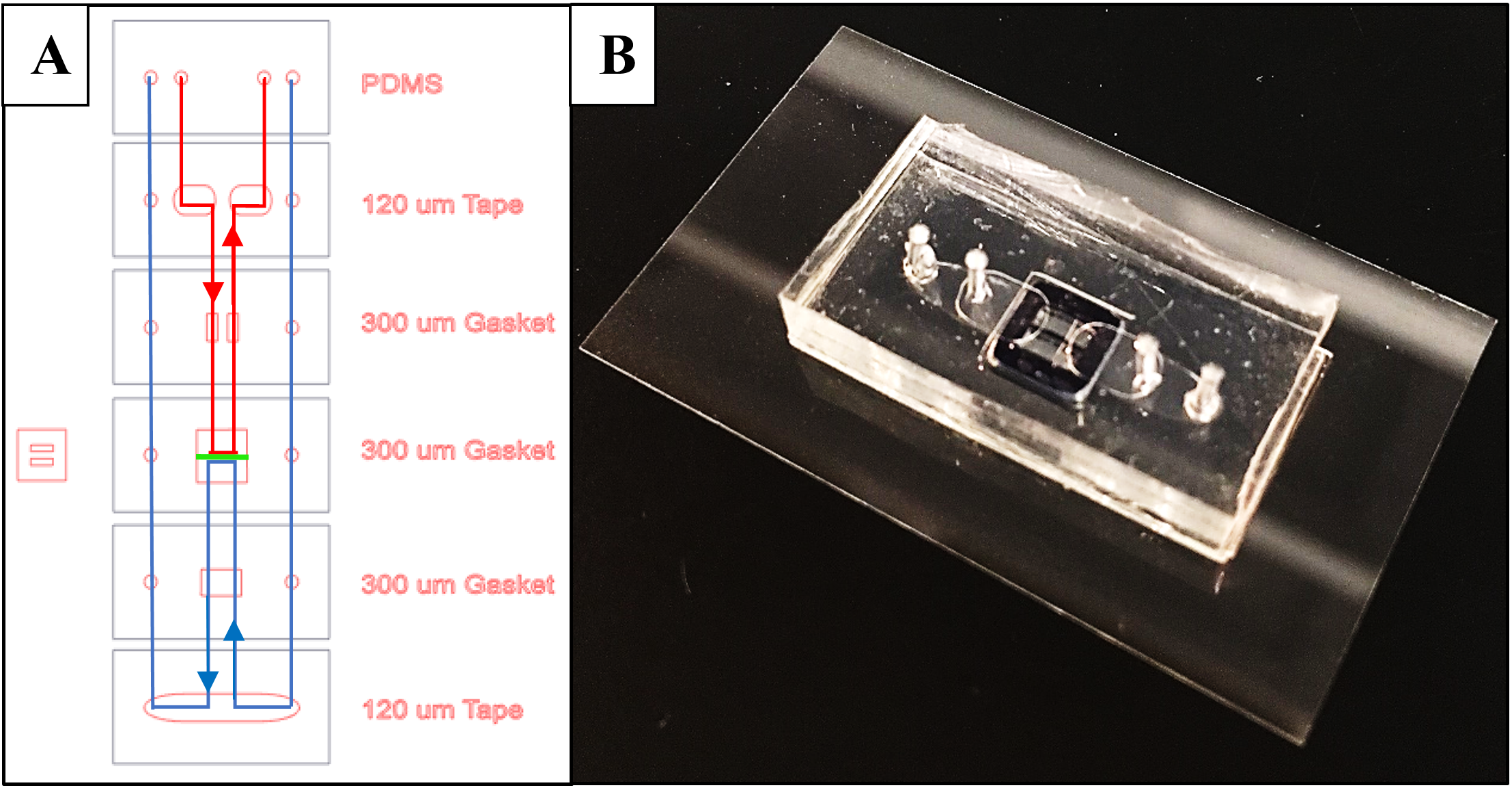
For double slot devices, adjustments were again made to the single slot design to ensure both membranes on the chip were active (Figure 3). All layers were adjusted accordingly referencing the single slot membrane channel measurements. The design was validated using a food dye test to ensure that analyte and dialysate channels did not leak.
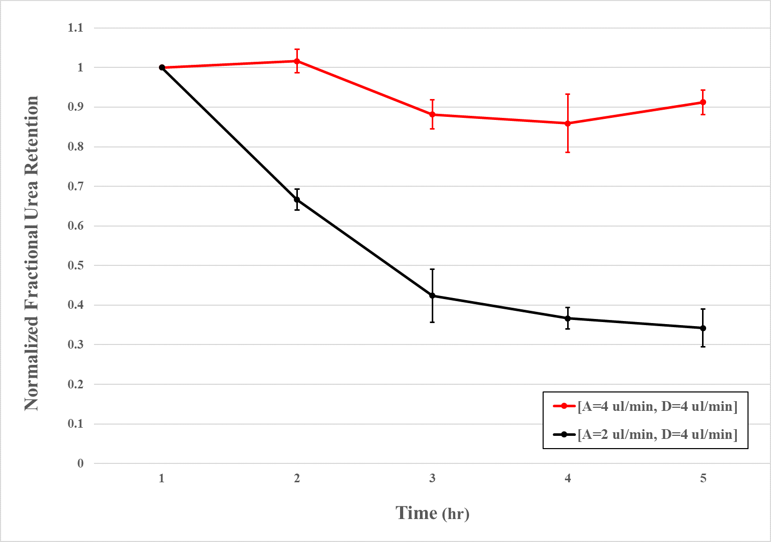
To counter this, the dialysate collection height was raised to minimize the pressure difference between the channel outputs. Analyte flow rates of 2 and 4 µL/min were tested with a constant dialysate flow rate of 4 µL/min. All experimental variations yielded analyte samples, and as before were collected hourly, for six hours, and assayed. Experiments were completed in triplicate and results were normalized as stated before.
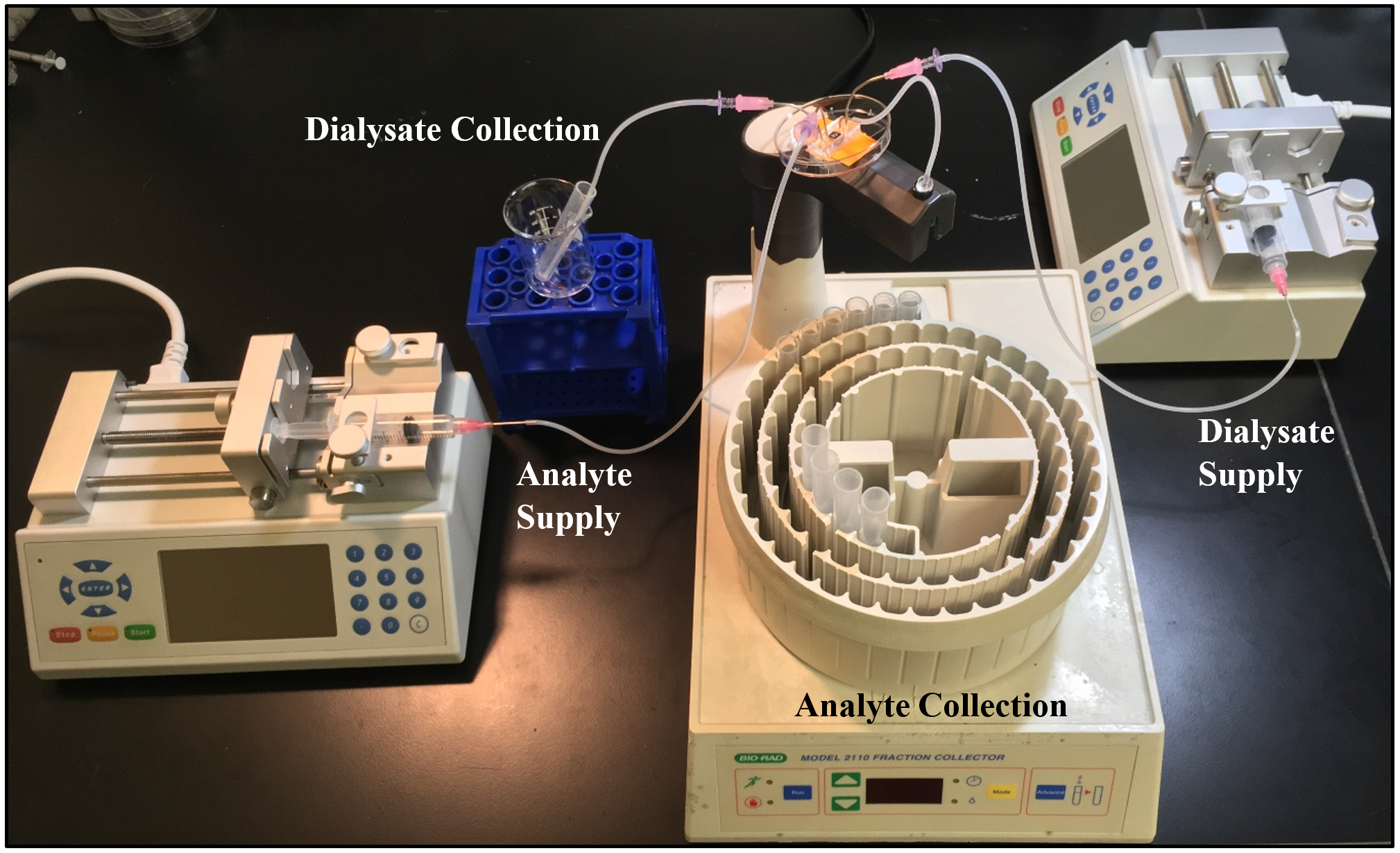
During experiments, samples were gathered using a fraction collector and flow rates were maintained using syringe pumps (Figure 4). Before starting each experiment, analyte and dialysate lines were primed through device channels until fluid reached collection vessels.
Results
Findings for single slot inverted-chip devices indicate a gradual loss of urea content over four hours followed by an increase during the final hour (Figure 5). The configuration reached a maximum normalized fractional loss of approximately 0.21, eventually concluding with 0.14.
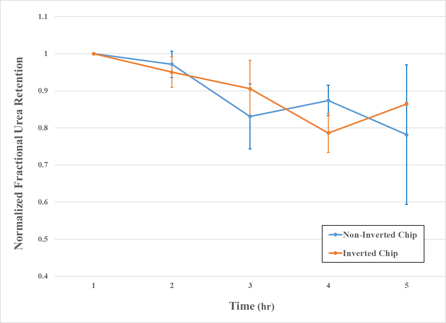
Although the shape of the urea-loss curve appears unique compared to devices with the original chip configuration, statistical analysis disproves this theory. JMP Pro software’s t-test shows that there is no significant difference between the non-inverted and inverted-chip configuration data.
Results for double slot devices indicate a significant improvement in urea clearance when analyte flow rate is adjusted from 4 µL/min to 2 µL/min. When the analyte flow rate was 2 µL/min, the membranes reached an approximate normalized fractional clearance of 0.66 compared to 0.14 reached by the 4 µL/min analyte flow rate.
Discussion
As a result of inverted-chip experimental findings, we are able to conclude that neither chip configuration offers significantly better urea clearance than its counterpart under these experimental conditions. Following, the analyte-trench combination is effective when clearing urea and should be implemented in future devices and experiments concerning blood analytes. Larger devices will incorporate this feature in an effort to minimize blood needed for experimentation; ultimately benefiting from trench geometry.
When compared to the single slot membrane devices, the double slot devices provided significantly better urea clearance with the 2 µL/min (analyte) and 4 µL/min (dialysate) flow rate combination. Among double slot results, we believe faster analyte flow rates effectively decreased the volume of fluid near the membrane where diffusion has the potential to occur. Moreover, these results further verified using a combination of flow rates in which the dialysate is twice that of the analyte.
Double slot membrane studies are new and unestablished as many parameters still need to be analyzed. For instance, only a few flow rate combinations were tested and future experiments should aim to explore this analyte/dialysate flow rate combination. Specifically, it would be interesting to see what would happen if the analyte flow rate was adjusted to 3 µL/min while maintaining a dialysate flow rate of 4 µL/min. Further studies should utilize different analytes, such as urea spiked FBS, to determine how the double slot membrane performs with a “blood-like” fluid that poses a higher potential of fouling.