Culture divider insert assembly and test
Introduction
We are designing a cell culture chamber insert to allow side-by-side co-culture of cells and ultimately triculture in the µSiM devices.
 Materials and Methods

- ALine devices assembly according to the “ALine Modular Device Assembly” instructions. 2-slot NPN membranes applied (NPSN100-2L, nanoporous silicon nitride 100 nm thick, 2 windows). Straight tweezers and chip tweezers are the same as in the “ALine Modular Device Assembly” instructions.
- Assembly tutorials
- Peel off the blue plastic cover from the Top / Nonadhesive side of the divider.

- Peel off the translucent cover from the Bottom/Adhesive (PSA, pressure-sensitive adhesive) side of the divider. (Sometimes, there is also a blue cover outside the translucent PSA cover. If so, peel the blue plastic cover first.)
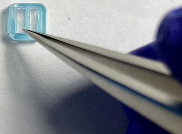
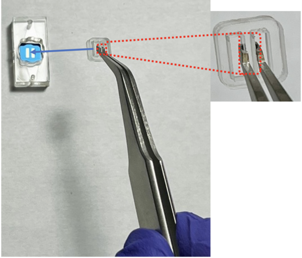
- Use chip tweezer to hold the divider nonadhesive side up and PSA side down. Align the wall (highlighted with a red dashed rectangle, in-between the two chambers of the divider) to the middle of the membrane (nonporous area between two windows).
Note: The alignment of the wall with the middle chip avoids breaking the membrane later.
- Gently press the divider to adhere to the membrane and hold 2 s then slowly take out the chip tweezer. Assembly Video
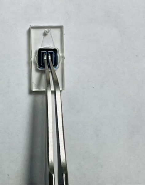
- Use a small tip pipette (recommend p10) to add 9-10 ul of liquid into each chamber. Avoid touching the membrane while adding/changing media. Add media Video
Bonded device leak test
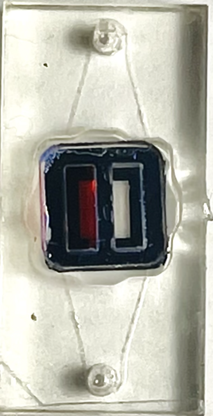
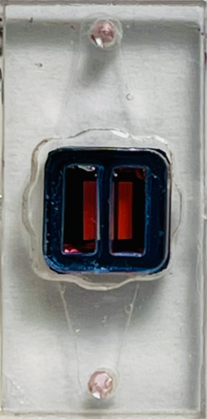
- No leakage through the wall between the two chambers (Photos were taken after 2 days of dye addition).
Sealed the backside of the chip. Added water on the backside and the other chamber. Let the red food dye diffuse for 2 days.
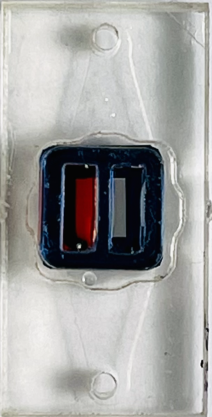
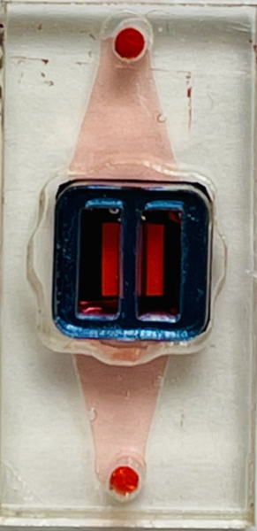
- Communication between the two chambers through the bottom channel.
No diffusion when Air was on the backside and water on the other chamber for the unsealed chip.
Top view Bottom view (flipped over)
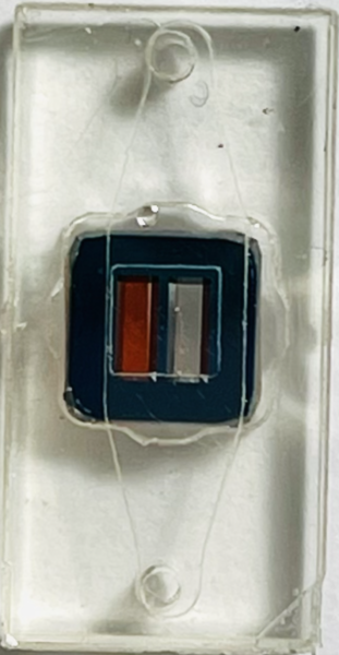
Diffusion occurred when water was on both backside and the other chamber for the unsealed chip.
Top view after 2 days of diffusion
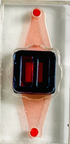
Bottom channel flushed with water Bottom channel re-diffused after 2 days

**********************
Possible difficulties of the assembly
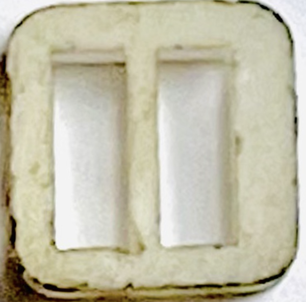
- The assembly success rate of the newly arrived dividers could be low as 50% sometimes. This is due to the small space to work between membranes, so many membranes break during assembly. Besides, the newly arrived dividers are not completely symmetrical (as shown below), which makes it difficult to align the wall with the middle chip, as a result, easy to break the membranes.
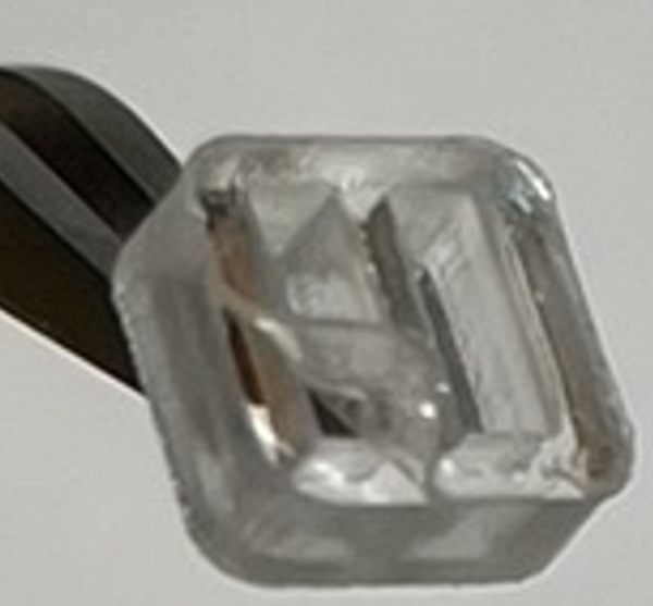
- The PSA layer sometimes came off along with the cover layer when peeling off the cover (as shown below). This might be: a) the cover layer is smaller/the same size as the PSA layer which makes it hard to pick up the cover edge with tweezers. b) the PSA is not sticky enough to stay on the acrylic divider. Possible solutions: a) Make the cover size slightly bigger than the PSA layer; b) Or make the PSA layer stickier to the acrylic materials.
**********************
Cell Culture Results
To demonstrate modularity in the modular µSiM introductory paper, we sought to do a side-by-side EECM-BMEC-like cell (hiPSC-derived brain ECs) and normal human primary astrocyte (NHA, Clonetics) co-culture. Our initial method was to coat both chambers, seed EECM-BMECs first and allow the culture to establish itself, then seed NHA the following day. Then we fix and stain for brain EC tight junction marker, Claudin-5, and astrocyte marker, GFAP. Note Claudin-5 staining I have always used methanol fixation but GFAP staining protocol used PFA. My first attempt used PFA.
Trial 1
Seeded 1/3 devices successfully with both cells types. Broke the other two devices. Pipetting into small chambers is very challenging. Grew two days and fixed with 4% PFA and stained for Claudin-5 and GFAP. No Claudin-5 stain and lost astrocytes during fixation/staining. Suspected old PFA.
Trial 2
Broke 1 device during EECM-BMEC seeding. NHA did not adhere to 2/2 devices. Overall 0/3 success. We suspect a bubble between the membrane and cell suspension. The surface tension of the chambers and membrane with such a small working area is very high. It is extremely challenging to pipet fluid and cover the whole surface. Sometimes it is hard to tell if fluid added actually contacts the bottom.
Maintained ECs anyways and also seeded NHA in well plate to test methanol fixation. Continued growth and fixed one device with fresh 4% PFA and the other with methanol. Fixed NHA in a well plate with methanol. Stained for Claudin-5 and GFAP. 4% PFA still did not work for Claudin-5 but methanol worked for NHA. I will use it for the next attempt. One other note is I found it was more common to get bubbles in the trench during the staining process than on one-slot devices. They are challenging to remove and resulted in breaking both membranes. These results were based on the remaining parts of the membrane that could be visualized still. In the next trials, I did not stain in the bottom, I only fixed and washed it once to avoid this problem.
Trial 3
First plasma-treated 2 assembled devices using corona wand to improve the hydrophilicity of membrane and insert. Left 2 devices untreated in case of issues. Plasma treating appeared to make coating easier and reduce the surface tension of the chamber. However, EECM-BMECs did not adhere to any (0/4 success) devices. Suspect surface tension again.
Trial 4
Plasma treated all assembled devices using corona wand. Coated and seeded all cell types the same day to maintain hydrophilicity. Kept chambers wet with water or PBS in-between steps to prevent drying. Broke 2/4 devices during cell seeding. The second device broke the next day, it was unclear what caused it to break. 1/4 overall success. Thankfully, the remaining device was successfully seeded, fixed with methanol, stained for Claudin-5 and GFAP, and imaged. Also, in case of staining went poorly, prior to fixation, I added extra media on top of the chamber and dropped a glass coverslip to get a flat imaging plane, and acquired a phase-contrast image of the cells.
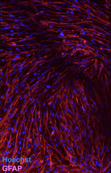
 Interestingly, only a handful of the astrocytes expressed GFAP. We have learned since that it is a reactive astrocyte marker, so this is actually positive that co-culture with the ECs seems to reduce the number of astrocytes expressing this marker. This is different than what I saw on the “methanol-fixation test” well plate culture and different than we see with NHA culture alone in µSiM devices (see image below).
 Conclusions
Cell culture inserts as designed are incredibly challenging to work with. There appears to be close to a 50% loss rate at each step (assembly, coating, seeding, fixing). The main problem for cell culture is the small area to work with and high surface tensions. Another problem is the inconsistency of the chamber capacity. It holds 7-10 ul of the liquid in different chambers. Given the small volume of the chambers, this inconsistency of the chamber volume makes a relatively big difference in the coating, cell seeding density, the fixation process, and media evaporation. A higher chamber volume consistency is needed. One possible way could be to raise the height of the divider and get a slightly bigger chamber capacity. Other thoughts are that future designs will consist of only one chamber, with the rest of the space free for the second cell culture, so we only have one constrained area. To make it easier to assemble the insert, we could also increase the space between the membrane windows on the chips.
On a positive note, we were able to achieve the staining and side-by-side culture we needed for the paper. This also led to a positive finding that astrocytes could potentially serve as an interim marker for inflammation, prior to the addition of microglia into our model. More work is needed to be done to reproduce this finding.