Liftoff Membrane Capture for Hemodialysis
As part of our work on the NSF STTR grant for our hemodialysis device, we need to develop a device to incorporate our liftoff membranes into to facilitate the fluidics. In this post (and likely, in another post later this month,) I will chronicle my contribution to this aspect of the project: finite element modeling of fluid dynamics to guide device design.
As a starting point, Josh developed a 3D printed scaffold that, combined with a few silicone gaskets, defines the blood and dialysate channels in an attractively compact package.
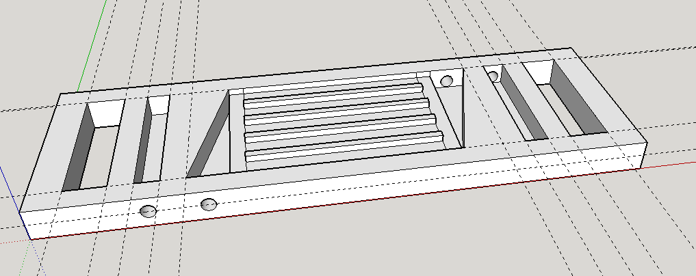
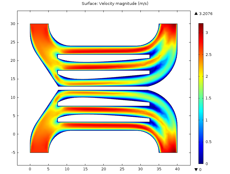
The middle region of this scaffold consists of an inport and an output, connected by the triangular wells to a 1 inch square region containing ridges to support the liftoff membrane. This is the channel for the blood, and at first glance it looks pretty good. A finite element model of the fluid flow in this region reveals some problems.
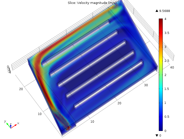
This is a plot depicting velocity magnitude of the fluid (note: in this simulation, I used the properties of water and flow rates on the order of what will be required for practical hemodialysis.) There’s an obvious strong bias towards flow through the channel furthest from the inport, probably due to a combination of momentum from the inport in the y-direction and a build up of high pressure at the distal apex of the triangular section.
This is problematic for two reasons:
- Uneven flow distribution means solute transport out of the fluid is uneven, resulting in poor (inefficient) clearance characteristics.
- Slow or stationary blood tends to clot, which is obviously unacceptable.
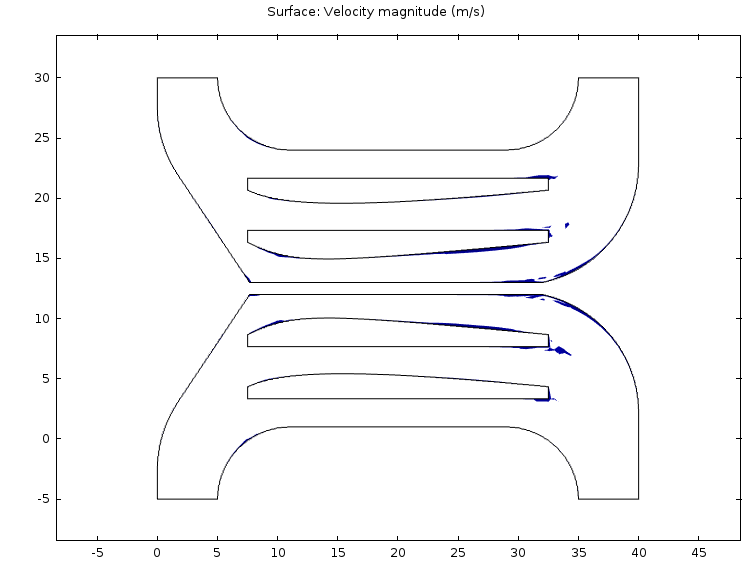
In order to fix this, we’ll need a design which distributes the flow more evenly and contains minimal regions of stationary flow. To be more specific, none of the flow should be slower than 0.13 m/s [1].
The first problem can be fixed easily enough by splitting the in- and outflows between two symmetrically placed ports (this time using blood properties,) as such:
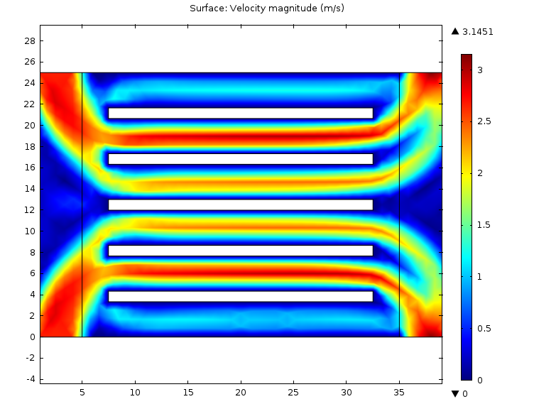
This flow is clearly much more even. By playing with the geometry near the inports, this can be improved even further:
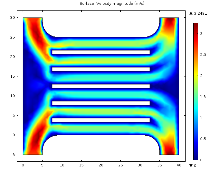
However, plotting only regions of flow with velocity less than 0.13 m/s, we see that the second problem remains:

The colored regions here are deadzones where clots are likely to form due to low flow. Working to minimize these regions while maintaining the good evenness of flow, I arrived at this final solution:
Probably further tweaking could be done to improve this design further — however, such small changes are likely well within the magnitude of error between simulation and reality, and thus FEA becomes a less useful tool (unless we really want to dive into the deep end on modeling fluid-structure interaction.)
For initial benchtop testing, I suspect that this final design of mine is going overboard — we should first attempt something more like the second design (double ports, modified port geometry) with a simulation “blood” that will not clot, in order to mitigate the trouble of deadzones. Once our design has been validated in that way, we may look to injection molding or otherwise producing the more complicated design for use with real blood.
Going forward, I’ll be attempting to acquire predictions of plasma solute transport during hemodialysis with this device by translating this design into three dimensions (or by some other means.) Translations of COMSOL fluid flow models from 2D to 3D can be tricky, so we’ll just have to hope it works well enough here. Otherwise, we can always fall back on my analytical models for a reasonable approximation of transport characteristics.
EDIT 10/20/15: Jim brought up the fact that in addition to low flow, high shear conditions can also lead to platelet activation. My COMSOL model predicts wall shear rates on the order of 10,000 1/s, which it looks like probably will induce platelet activation [2]. However, this DOES depend on surface chemistry, so coatings may be able to alleviate this issue — for instance, maybe we can include heparin on the surface of the device?
Either way, this is something we’ll have to be aware of going forward. It may be necessary to use two devices, each with roughly half the load of my design here, in order to prevent clotting.
[1] Bajd et al. “Analysis of blood clot degradation fragment sizes in relation to plasma flow velocity.” 2012. General Physiology and Biophysics 31(3): 237-45.
[2] Holme et al. “Shear-Induced Platelet Activation and Platelet Microparticle Formation at Blood Flow Conditions as in Arteries With a Severe Stenosis.” 1997. Arteriosclerosis, Thrombosis, and Vascular Biology 17: 646-53.
I’ve made an edit to this post to reflect discussion on shear-induced platelet activation that occurred at NRG.