New design of the flow platform with a functional lid (V2)
Introduction
In a previous post, an initial version of the flow module and its sealing components were described. In order to improve the initial version based on collaborators’ feedback, several modifications have been made to simplify the device assembly for the end-user (Fig. 1) and address concerns about:
1) Local regions of high shear stress along the flow path
2) Assembly and alignment of the flow module
3) Metal connection pins, including Potential damage to the membrane during the addition of metal connection pins and robustness of connections during manipulation and handling on microscope

Fig. 1. The first version of the flow platform vs. the second version with a functional lid.
Materials and Methods
A flow routing channel was sandwiched between two PMMA layers, then, two additional PMMA layers and o-rings were attached to it to provide a seal connection for tube connectors (Fig. 2.a). All of the PMMA layers were made using laser cutting and bonded together by PSA tape. This routing channel is necessary in order to provide tube fittings farther from the flow module for ease of use.
The flow module was fabricated using the standard soft lithography technique on a customized aluminum mold to obtain the module with a clover shape and a thin gasket on top of it (Fig. 2.b). Finally the PDMS component and PMMA component with a PSA tape on it were plasma treated to increase their surface energy for enhanced attachment, and tube fittings were inserted (Fig. 2.c-e).

Fig. 2. Schematic of the functional lid elements. (a) Main components of the flow routing section, (b) flow module integrated with a PDMS gasket, (c) addition of the flow routing section and tube fittings to the PDMS element, (d,e) assembled view of the functional lid.
In order to mitigate the shear stress peak at corners, the diameter and height of the inlet and outlet ports have been increased. Furthermore, a new end-mill will be used for mold fabrication to have a 100 um fillet in the junction between the port and microchannel (Fig. 3).
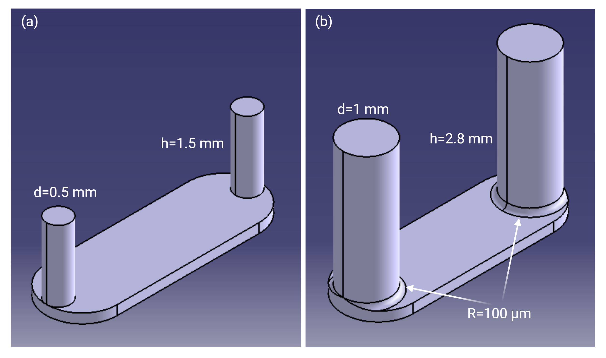
Fig. 3. The geometry of the flow module. (a) version 1, (b) version 2
Results and Discussion
The new design consists of a functional lid for introducing flow and a base for encompassing the uSiM (Fig. 4). In comparison to the previous device, the new design offers several unique features as follows:
- Integration of the flow module to the upper housing
- No need to insert and align the flow module by hand
- The functional lid provides barbed tube fitting which enables users to directly connect tubing to the platform
- Simplified device assembly for the end-user (Video 1)
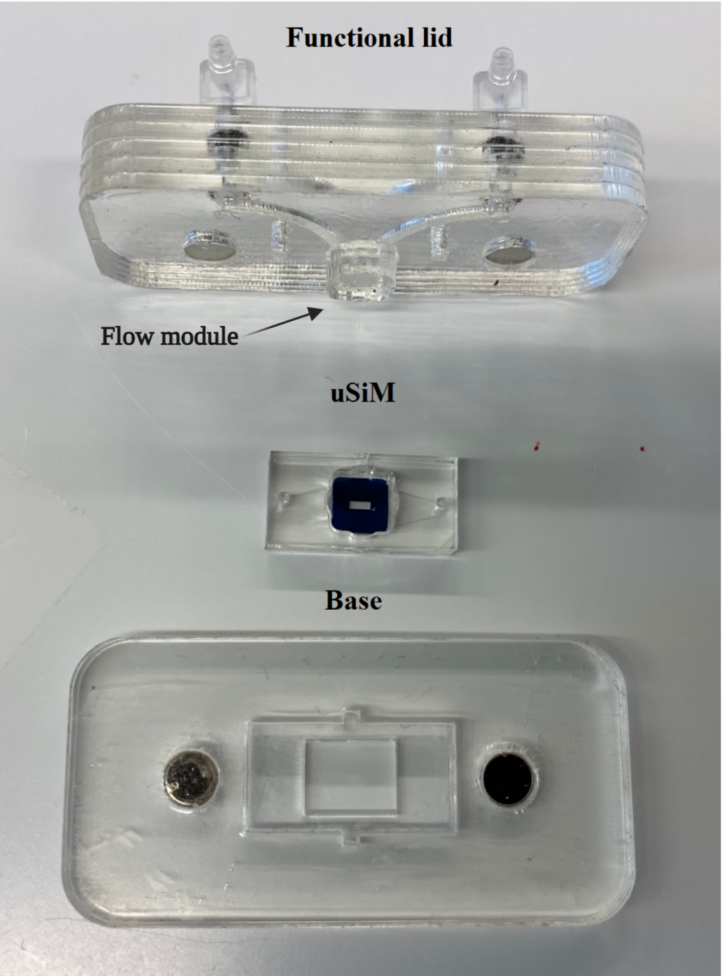
Fig. 4. Components of the new design include the base, uSiM, and functional lid with integrated flow routing paths and a pre-attached flow module.
Shear stress peaks at corners were one of the main issues of device V1 in which the shear stress at corners was 3.4 times greater than the shear stress on the membrane (Fig. 5.a). In the new design (V2), this ratio is reduced to 1.7 by applying the aforementioned modifications (Fig. 5.b).
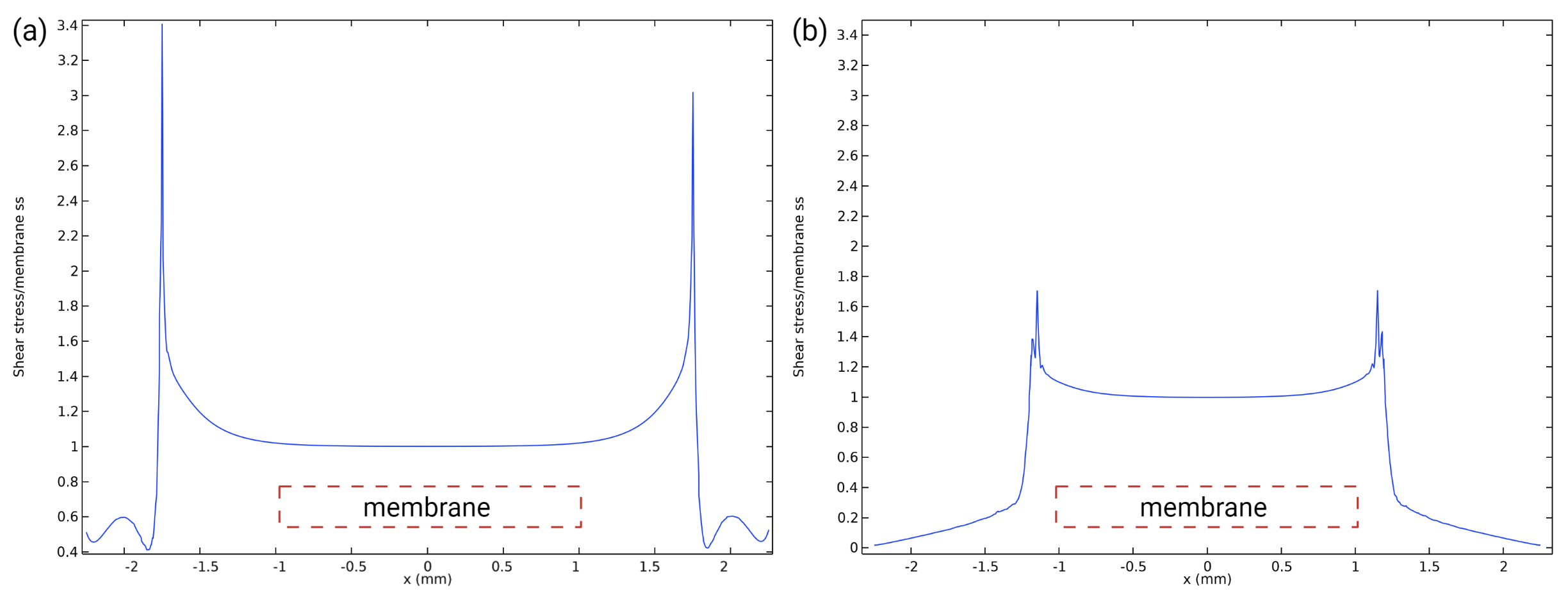
Fig. 5. Shear stress in the flow module normalized to the shear stress on the membrane in design (a) V1, (b) V2
The new design also offers more flexibility to introduce additional components such as fluid reservoirs, valves and enables simple multiplexing of devices to increase the experimental throughput (Fig. 6). (Video 2).

Fig. 6. The image of the assembled device that shows the branched flow route (red dye) in the functional lid that allows multiple modules to be perfused with a common fluid input to support multiplexing.
Nice system! Have you used it with HUVEC yet? and if yes at what Shear stresses? I apologize if I missed that yesterday
Hi Julie,
Yes, I have used the lid to align HUVECs at 600 ul/min (10 dynes/cm2) and I got alignment in one sample. But, I need to troubleshoot some aspects of my fabrication steps to have appropriate geometrical tolerances and enhance the reproducibility of experiments.