Incorporating a ECM hydrogel into an in vitro microvasculature system
For the past month, I have been working along with Tejas towards incorporating an ECM-like hydrogel into the back (edged side) of a pnc-Si chip. The purpose of this effort is to add another layer of complexity to Tejas’ in vitro microvasculature system, in order to study neutrophil migration across the endothelium.
We first pondered on a variety of materials to be used as ECM mimetic constructs (like collagen, PEG with collagen-mimetic peptides and chitosan), but finally settled for Geltrex (Life Technologies), which contains some of the major components of the ECM and can be thermally activated at 37 °C.
As a manner to familiarize ourselves with the properties of the gel, we started off working on the following setup:
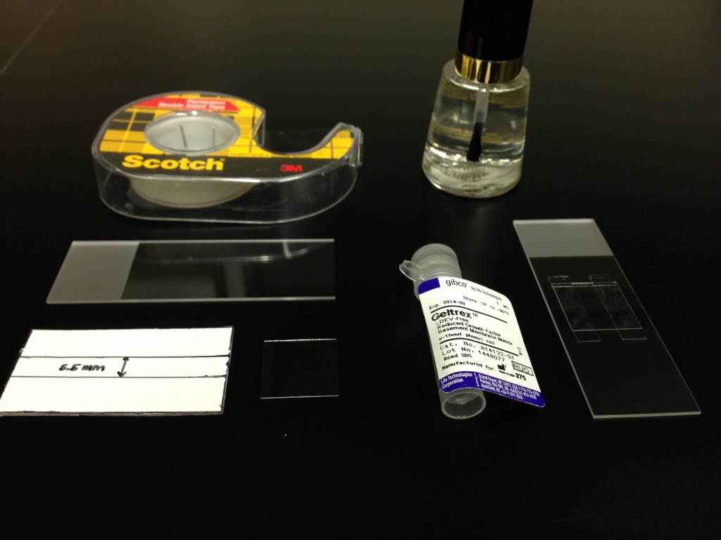
A microfluidic channel (bottom right) made out of two strips of double sided tape on a 75x25x1 mm microscope slide for the bottom surface and a 18×18 mm cover glass for the top.
For this type of arrangement, we normally thaw a small aliquot of Geltrex (50 μl) overnight at 4 °C and then dilute it to a final concentration of 10 mg/ml with DMEM and fluorescent beads. The beads are diluted in water from stock to a final concentration of 0.08 pM.
The mix is briefly vortexed and thoroughly pipetted to try and disperse the fluospheres as much as possible throughout the gel. Then, a microfluidic channel is filled with 10 μl of the final mix. Pre-chilling channels, test tubes and pipette tips helps to manipulate the gel, preventing it to become prematurely viscous during this stage.
The polymerization step takes place at 37 °C for 40 minutes. After that time, it’s a good idea to seal the channels with nail polish or parafilm in order to prevent evaporation. The samples can be preserved at 4 °C, if they are not going to be visualized immediately.
This is a manual z-scan through the gel using 1 μm fluorescent beads for imaging under the fluorescent microscope:
We also tried smaller sized fluorescent beads in the same setup to see if we could see brownian motion. 20 and 40 nm beads were tricky to visualize, and we end up using 100 nm beads instead. This is a 10 min time-lapse (with 6 s intervals) taken on the same z-plane:
We are now working on incorporating the gel into the back of a chip. The procedure we are following for doing this is very similar to the one described before, except for a couple of details.
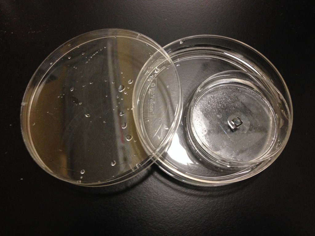
Since this is an open setup and we are using a very small volume (30 μl), we encountered a bit of trouble with the gel getting a little bit dehydrated during the polymerization step. In the end, we had to restore to incubating the gel-surffused chips in a 10 ml culture dish half-filled with water:
Considering that we are trying to asses the extent to which the gel is incorporated into the trenches of the chip, we tried a system in which we incorporated the hydrogel with 100 nm fluorescent beads at the bottom of the chip (as described before) and water with 1 μm particles on the top. We used a 1 mm thick PDMS gasket as a spacer between the bottom of the chip and the culture dish we did the experiment on, so that the gel would stay intact after turning the chip around when adding water on the top.
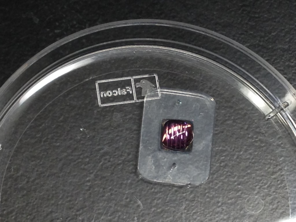
This is what a window on a chip in this setup looks like under the fluorescent microscope:
The first few frames are taken on the top of the chip (flat side), where there are some fluorescent beads sedimented on top of the chip’s window and some moving on top in the solvent. Later frames show a couple of z-planes within the trench on the back of the chip; the edges of the window look blurred here and different beads seem to come in and out of focus as we go down the trench.
It was rather difficult to tell which fluorescent beads were on top and which on the bottom, seeing that we used yellow/green particles on both sides, even if they had different sizes. We are going to try to use beads of a different color on the top of the chip next time to see if we can visualize them better.