SEM of 4-hour Hemodialysis Membranes
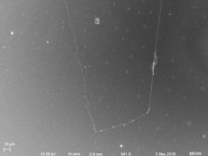
To image the blood side (in-channel) side of the membranes, I transferred the membranes of a HD chip onto another wafer segment (SiN wafer: 4534) The transfer wasn’t clean but I got some good images.
These membranes were exposed to blood flow for 4 hours in a typical rat HD setup. Post experiment, the membranes remained in contact with the blood until the devices were transported back to Goergen, disassembled and washed with PBS and fixed in 4% paraformaldehyde for approximately 10 min at room temperature and finally rinsed in DI water for one minute. The membranes were then allowed to air dry before depositing gold (one minute) and put into the SEM.
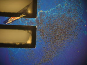
First let me show you the optical images, I start with two images of the blood side showing the input side, you can see the detritus on the surface, where it ends between the channels in the second image is where the fluidic bus ends and the chip surface is in contact with the PDMS. At about that point is where the confluence ends within the channels.


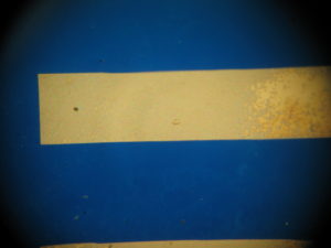
The next two are the blood side where the flow exits. While not as obvious from these pics, the amount of contamination at the exit is less than at the entrance.

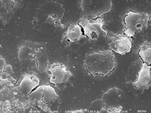
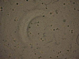
These next two images are of the dialysate side, you can easily see the contamination through the membrane.

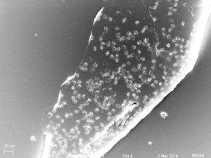
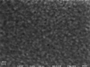
These are closer images showing the shape of the objects on the surface. (The channels are ~500 µm wide)

I imaged two membrane segments, one clean and one with little nasties. I won’t make comments here on what those objects are.
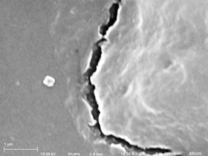
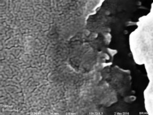
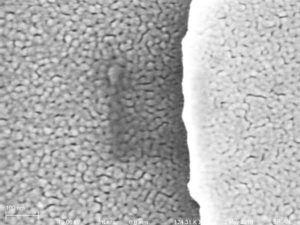
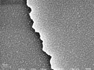
The first group of eight SEM images shows a very clean looking membrane… The last image has the membrane on the left and the carrier wafer on the right, all other images (but the first) have the membrane on the right.


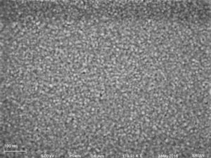
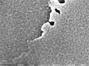

Then I found this membrane, with a lot of interesting stuff on it. Again, these membranes were not rinsed and fixed immediately after the cessation of blood flow.